


3-7
Network Processing Engine and Network Services Engine Installation and Configuration
OL-4448-12
Chapter 3 NPE-300 and NPE-400 Overview
NPE-300 and NPE-400 Memory Information
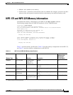
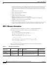
32 MB
4
+
128 MB
U45 and U44
or
U45
2 64-MB DIMMs or
1 128-MB DIMM
MEM-SD-NPE-64MB
MEM-SD-NPE-128MB
32 MB
4
+
256 MB
U45 and U44 2 128-MB DIMMs MEM-SD-NPE-256MB
1. Refer to the Cisco AS5800 Universal Access Server documentation listed in the “Related Documentation” section on page iii for Cisco AS5800
Universal Access Server SDRAM options.
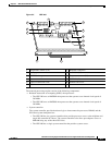
2. There are two user-upgradable SDRAM slots in bank 1. (Bank 0 is used exclusively for packet memory and is set at a fixed configuration of 32 MB in
the factory.)
3. These products are also available as SDRAM upgrades. To order an upgrade, add an equal sign (=) after the product number, for example,
MEM-SD-NPE-128MB=.
4. This 32 MB is fixed memory in SDRAM bank 0, socket U16. Socket U15 is never populated.
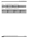
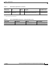
Ta ble 3-3 NPE-400 Memory Specifications
Memory Type Size Quantity Description
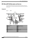
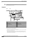
Component
Location on
the
NPE-400 Board
SDRAM-configurable 128, 256, or 512 MB 1 128-, 256- or 512-MB SODIMM J1
Boot ROM 512 KB 1 OTP ROM for the ROM monitor program U7
Primary cache 16 KB (instruction),
16
KB (data)
— RM7000 processor, integrated cache U38
Secondary cache 256 KB (fixed) — RM7000 processor, unified, internal cache U38
Tertiary cache 4 MB (fixed) — RM7000 processor, external cache U2, U26, U27,
U28, U37
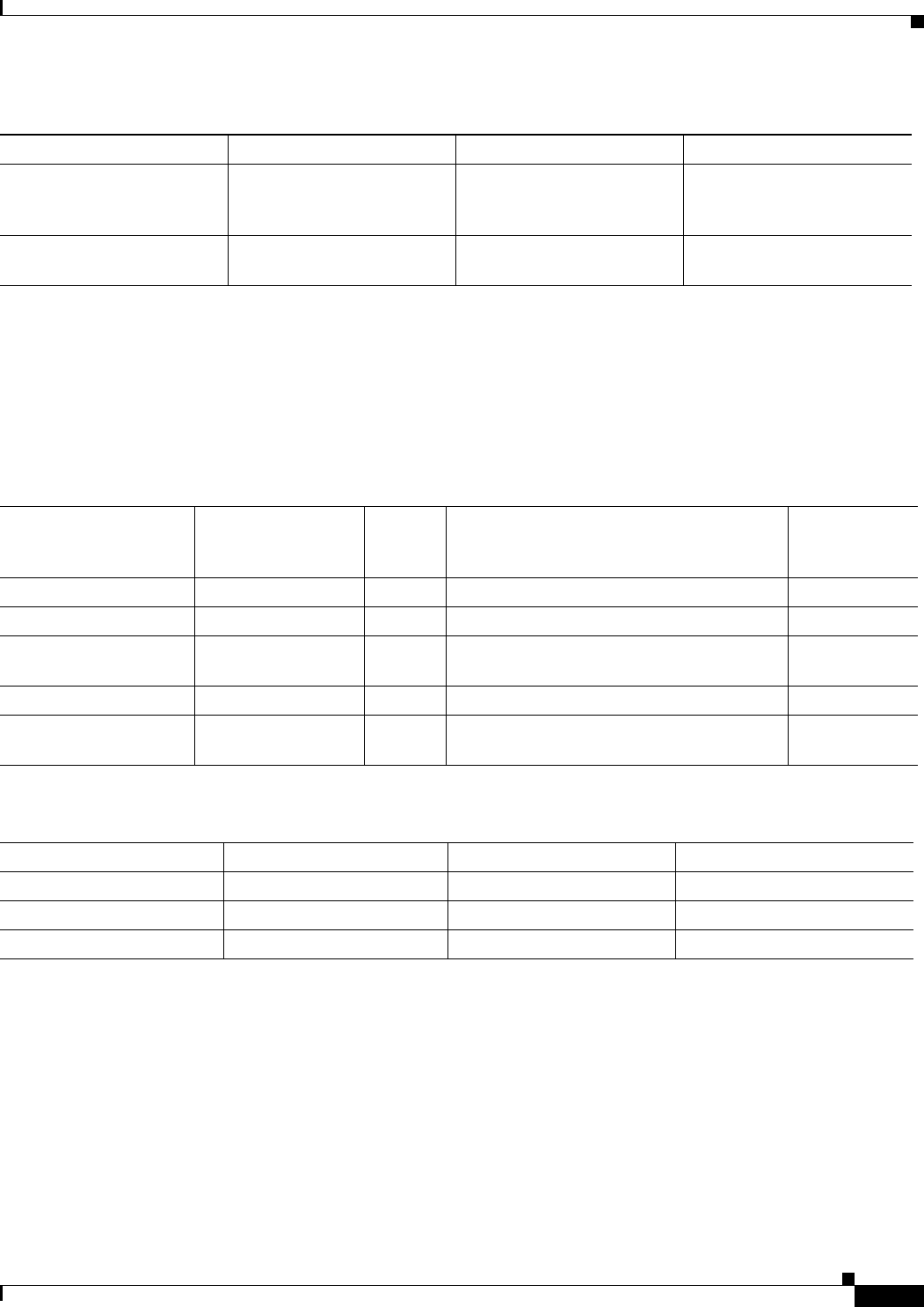
Ta ble 3-4 NPE-400 Memory Configuration
Total SDRAM Bank 1 Quantity Product Number
128 MB J1 1 128-MB SODIMM MEM-NPE-400-128MB
256 MB J1 1 256-MB SODIMM MEM-NPE-400-256MB
512 MB J1 1 512-MB SODIMM MEM-NPE-400-512MB
Table 3-2 NPE-300 SDRAM DIMM Configurations—Configurable Memory Only (continued)
Total SDRAM
1
Bank 1
2
Quantity Product Number
3