


7-18
Network Processing Engine and Network Services Engine Installation and Configuration
OL-4448-12
Chapter 7 NPE-G1 and NPE-G2 Installation and Configuration Information
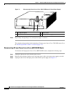
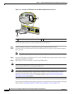
Installing the NPE-G1 or NPE-G2
Installing the NPE-G1 or NPE-G2
To install the NPE-G1 or NPE-G2 in the router, use the following procedures:
• Basic Guidelines, page 7-18
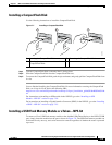
• Installing a CompactFlash Disk, page 7-19
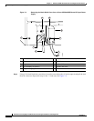
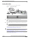
• Installing a USB Flash Memory Module or eToken—NPE-G2, page 7-19
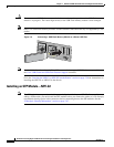
• Installing an SFP Module—NPE-G2, page 7-20
• Installing a GBIC—NPE-G1, page 7-23
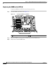
• Replacing the DIMM on the NPE-G2, page 7-24
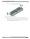
• Upgrading the SDRAM SODIMMs on the NPE-G1 (Optional), page 7-26
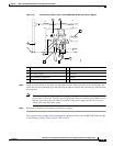
• Inserting the NPE-G1 or NPE-G2 into the Router, page 7-28
• Attaching the Rear Cable-Management Brackets and Cables (Optional), page 7-29
• Reconnecting Input Power and Powering Up the Router, page 7-35
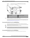
Basic Guidelines
Note If you have difficulty installing a network processing engine or I/O controller in the lowest slot of a Cisco
7200 VXR router that is rack-mounted, remove the port adapters, network processing engine and I/O
controller from the chassis and reinstall them. Install the network processing engine and I/O controller
in the lowest slots first, then populate the slots above them, in a bottom-to-top order.
Use the following guidelines when installing the NPE-G1 or NPE-G2:
Step 1 Ensure that the router is powered down and the input power cable is disconnected from the router and
the power source. See the
“Powering Down the Router and Disconnecting Input Power” section on
page 7-8.
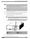
Step 2 Attach an ESD-preventive wrist strap between you and an unfinished chassis surface.
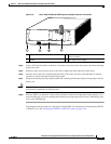
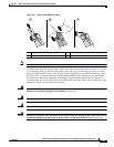
Step 3 Remove the NPE-G1 or NPE-G2 from its static shielding bag.
Step 4 When touching the NPE-G1 or NPE-G2, use both hands, grasp the NPE-G1 or NPE-G2 by its metal
carrier edges, and orient it so that its printed circuit board components face upward.
Caution Handle the NPE-G1 or NPE-G2 by the carrier edges and handle only; never touch the printed circuit
board components or connector pins.