


5-16
Network Processing Engine and Network Services Engine Installation and Configuration
OL-4448-12
Chapter 5 NPE-G1 Overview
Connection Equipment and Specifications
Mode-Conditioning Patch Cord Description
A mode-conditioning patch cord can be used with the WS-G5486= or GBIC-LX/LH= to allow reliable
laser transmission between the single-mode laser source on the GBIC and a multimode optical fiber
cable.
When an unconditioned laser source designed for operation on single-mode optical fiber is directly
coupled to a multimode optical fiber cable, an effect known as differential mode delay (DMD) might
result in a degradation of the modal bandwidth of the optical fiber cable.
This degradation results in a decrease in the link span (the distance between a transmitter and a receiver)
that can be supported reliably. The effect of DMD can be overcome by conditioning the launch
characteristics of a laser source. A practical means of performing this conditioning is to use a device
called a mode-conditioning patch cord.
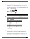
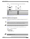
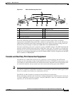
A mode-conditioning patch cord is an optical fiber cable assembly that consists of a pair of optical fibers
terminated with connector hardware. Specifically, the mode-conditioning patch cord is composed of a
single-mode optical fiber permanently coupled off-center (see Offset in
Figure 5-11) to a graded-index
multimode optical fiber. Figure 5-11 shows a diagram of the mode-conditioning patch cord assembly.
2. A mode-conditioning patch cord is required.
When using the WS-G5486 or GBIC-LX/LH with 62.5-micron diameter MMF, you must install a mode-conditioning patch
cord between the GBIC and the MMF cable on both the transmit and the receive ends of the link when link distances are
greater than 984
ft (300 m). We do not recommend using the WS-G5486 or GBIC-LX/LH and MMF with no patch cord for
very short link distances (tens of meters). The result could be an elevated bit error rate (BER).
3. Dispersion-shifted single-mode optical fiber cable.
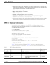
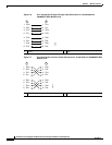
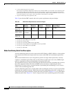
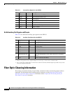
Table 5-8 provides the GBIC transmit and receive power requirements and power budget.
Ta ble 5-8 GBIC Power Requirements and Power Budget
GBIC
Transmit Power
Minimum Maximum
Receive Power
Minimum Maximum Power Budget
WS-G5484 or
GBIC-SX
–9.5 dBm
1
–4 dBm
1
–17 dBm 0 dBm 7.5 dBm
2
WS-G5486 or
GBIC-LX/LH
–9.5 dBm
3
–11.5dBm
4
–3 dBm
5
–20 dBm –3 dBm 7.5 dBm
6
and 8.0 dBm
7
WS-G5487 or
GBIC-ZX
0 dBm 5.2 dBm –24 dBm –3 dBm –24 dBm
1. For fiber types 50/125 μm, NA = 0.20 fiber and 62.5/125 μm, NA = 0.275 fiber.
2. For fiber types 50 μm MMF and 62.5 μm MMF.
3. For fiber types 9/125 μm SMF.
4. For fiber types 62.5/125 μm MMF and 50/125 μm MMF.
5. For fiber types 9/125 μm SMF, 62.5/125 μm MMF, and 50/125 μm MMF.
6. For fiber types 50 μm MMF and 62.5 μm MMF.
7. For fiber type 10 μm SMF.