


5-11
Network Processing Engine and Network Services Engine Installation and Configuration
OL-4448-12
Chapter 5 NPE-G1 Overview
Connection Equipment and Specifications
Note To comply with EMI EN55022 Class B regulations, shielded Ethernet cables must be used with the
UBR7200-NPE-G1 in the Cisco
uBR7246VXR router. Three shielded cables are included with the
UBR7200-NPE-G1.
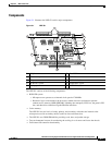
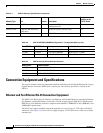
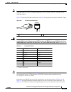
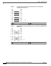
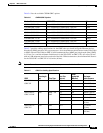
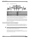
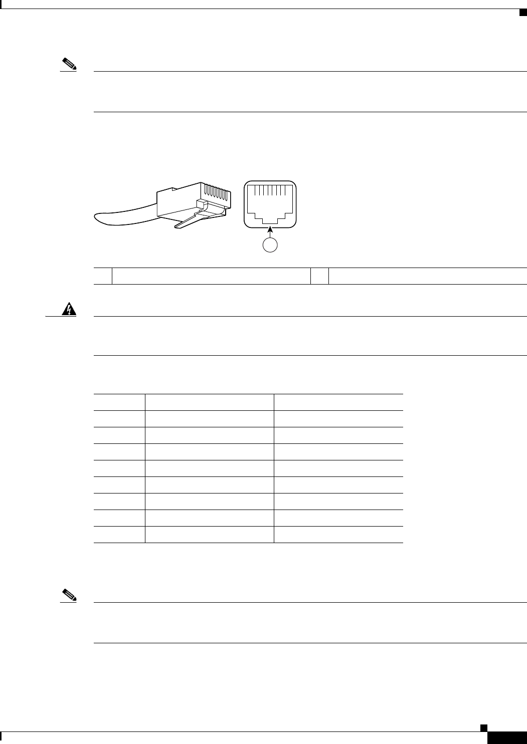
Figure 5-5 shows an RJ-45 port and connector. Table 5-4 lists the pinouts and signals for the RJ-45 port.
Figure 5-5 RJ-45 Port and Connector
Warning
To avoid electric shock, do not connect safety extra-low voltage (SELV) circuits to telephone-network
voltage (TNV) circuits. LAN ports contain SELV circuits, and WAN ports contain TNV circuits. Some
LAN and WAN ports both use RJ-45 connectors. Use caution when connecting cables.
Statement 1021
Note With reference to the RJ-45 pinout in Table 5-4, proper common-mode line terminations should be used
for the unused Category 5 UTP cable pairs 4/5 and 7/8. Common-mode termination reduces
electromagnetic interference (EMI).
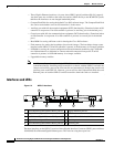
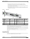
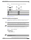
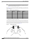
Depending on your RJ-45 interface cabling requirements, use the pinouts shown in Figure 5-6 and
Figure 5-7 for Gigabit Ethernet straight-through and crossover twisted-pair cable connections. Use
Figure 5-8 for Ethernet/Fast Ethernet straight-through and crossover twisted-pair cable connections.
1 RJ-45 connector
Ta ble 5-4 RJ-45 Port Pinouts
Pin 10/100 Signal Gigabit Ethernet Signal
1 Tx Data+
1
1. Tx Data = Transmit Data
Tx A+
2 Tx Data– Tx A–
3 Rx Data+
2
2. Rx Data = Receive Data
Rx B+
4 N/C Tx C+
5 N/C Tx C–
6 Rx Data– Rx B–
7 N/C Rx D+
8 NC Rx D-
57574
12345678
1