


7-31
Network Processing Engine and Network Services Engine Installation and Configuration
OL-4448-12
Chapter 7 NPE-G1 and NPE-G2 Installation and Configuration Information
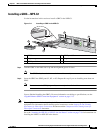
Installing the NPE-G1 or NPE-G2
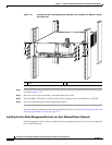
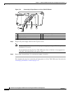
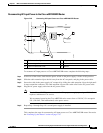
Step 1 Loosen the left and right captive installation screws on the NPE-G1 or NPE-G2.
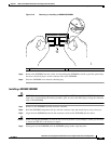
Step 2 Hold the cable-management bracket so that it is positioned above the NPE-G1 or NPE-G2 captive
installation screws as shown in
Figure 7-17 and Figure 7-18. The bracket is properly positioned when
the horizontally-faced notch is at the left, the vertically-faced notch is at the right, and the bracket’s outer
edge is flush with the edge on the NPE-G1 or NPE-G2. If you reverse the bracket so that it is not flush
with the NPE-G1 or NPE-G2, you will not be able to access the GBIC or SFP module connectors on the
NPE-G1 or NPE-G2 front panel.
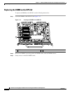
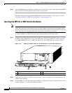
Step 3 Slide the left end of the bracket between the captive installation screw and the front panel of the NPE-G1
or NPE-G2.
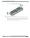
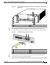
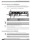
Step 4 Rotate the cable-management bracket down, until its other notch slides behind the right captive
installation screw. Make sure the bracket’s outer edge is flush with the edge of the NPE-G1 or NPE-G2
and does not obstruct the GBIC or SFP ports.
Step 5 Tighten both captive installation screws.
Step 6 Install the cables, and fasten them to the bracket with the velcro straps provided.
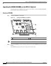
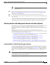
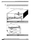
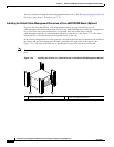
Installing the Rear Cable-Management Brackets on a Front-Mounted Router (Optional)
Use the instructions in this section to attach the cable-management brackets to a front-mounted
Cisco
7200 VXR router.