


9-15
Network Processing Engine and Network Services Engine Installation and Configuration
OL-4448-12
Chapter 9 Removing and Installing the NPE or NSE
Removing and Replacing the NPE or NSE
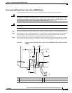
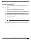
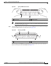
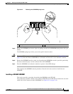
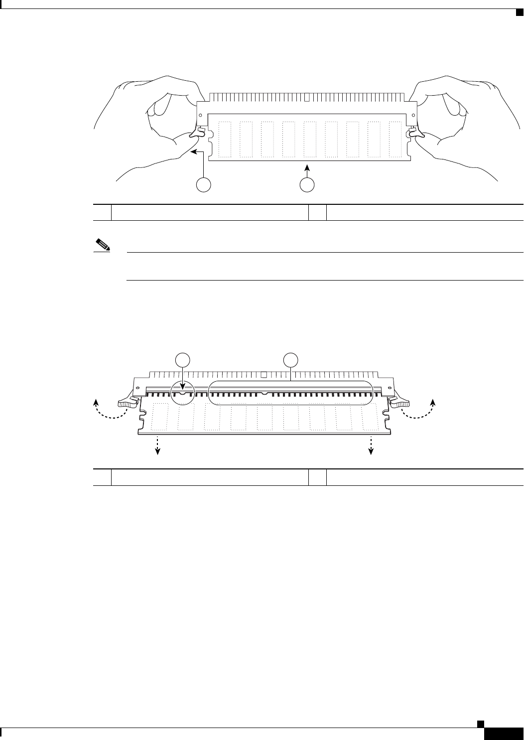
Figure 9-9 Opening DIMM Socket Latches
Note The SDRAM DIMM sockets on the NPE-175, NPE-225, and NPE-300 are parallel to the circuit
board. They are not tilted at an angle.
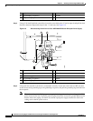
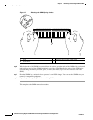
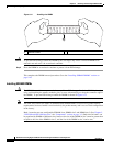
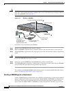
Step 5 With the DIMM socket latches open, grasp the ends of the DIMM between your thumbs and forefingers
and pull the DIMM completely out of the socket. (See
Figure 9-10.)
Figure 9-10 Removing the DIMM
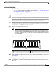
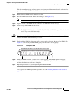
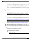
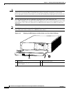
Handle the edges of the DIMM only; avoid touching the memory modules, pin or traces (the metal
fingers on the connector side of the DIMM). (See
Figure 9-11.)
1 Release latches 2 SDRAM DIMM
66412
21
1 Notch 2 Metal fingers
66414
1 2