


9-6
Network Processing Engine and Network Services Engine Installation and Configuration
OL-4448-12
Chapter 9 Removing and Installing the NPE or NSE
Removing and Replacing the NPE or NSE
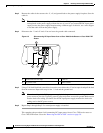
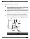
Step 3 Remove the cable tie that secures the –V, +V, and ground leads to the power supply faceplate. Save the
cable tie.
Note The cable tie that accompanied your Cisco 7200 series DC-input power supply can be removed
and replaced on the power supply without the use of a tool. If you secured the DC-input power
supply leads to the power supply faceplate using a different type of cable tie, use a wire stripper
to cut that cable tie from the power supply.
Step 4 Disconnect the –V and +V leads. You can leave the ground cable connected.
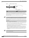
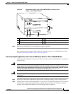
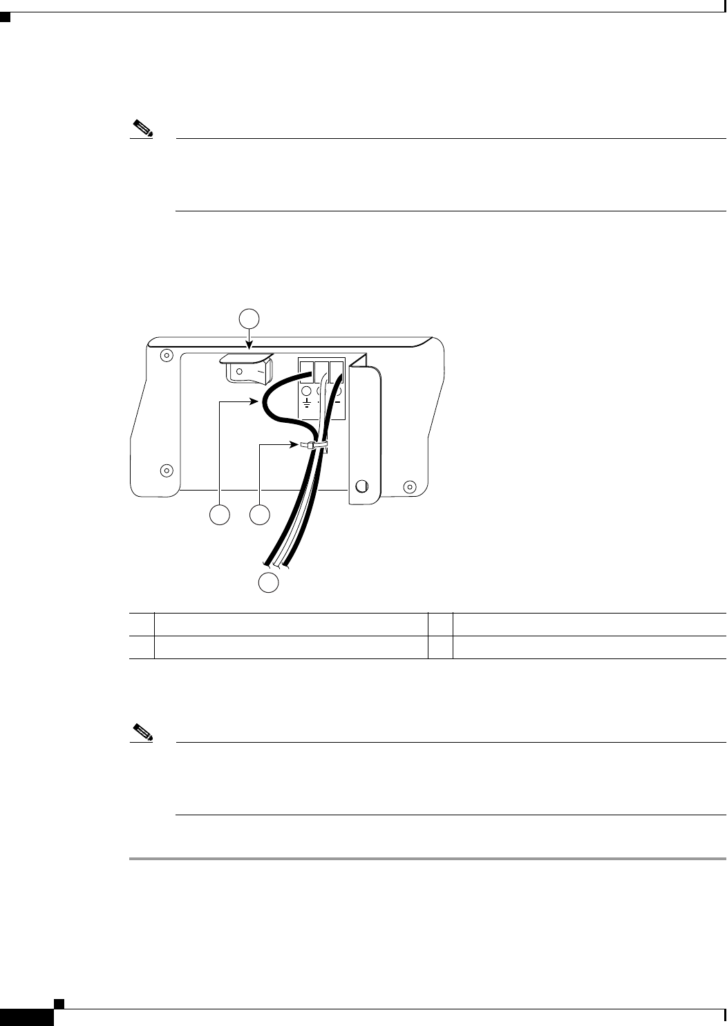
Figure 9-3 Disconnecting DC-Input Power from a Cisco 7200 Series Router or Cisco 7200 VXR
Router
Step 5 Using a 3/16-inch flat-blade screwdriver, loosen the screw below the +V lead receptacle and pull the lead
from the connector. Repeat this step for the –V lead and the ground lead.
Note The color coding of the DC-input power supply leads depends on the color coding of the DC
power source at your site. Typically, green or green and yellow are used for ground. Make certain
that the lead color coding you choose for the DC-input power supply matches the lead color
coding used at the DC power source.
Step 6 Repeat Step 1 through Step 5 if a second power supply is installed.
This completes the procedure for disconnecting DC-input power from a Cisco 7200 series router or
Cisco 7200 VXR router. Go to the
“Removing the NPE or NSE” section on page 9-9.
1 Ground lead service loop 3 Cable tie
2 DC power leads 4 Power switch
57013
1
2
3
4