


7-34
Network Processing Engine and Network Services Engine Installation and Configuration
OL-4448-12
Chapter 7 NPE-G1 and NPE-G2 Installation and Configuration Information
Installing the NPE-G1 or NPE-G2
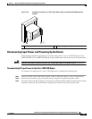
You have finished installing the cable-management brackets. Go to the “Reconnecting Input Power and
Powering Up the Router” section on page 7-35.
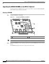
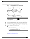
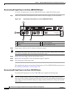
Installing the Default Cable-Management Bracket on a Cisco uBR7246VXR Router (Optional)
If you are not using the NPE-G1 cable-management bracket, you can alternatively use two
cable-management bracket configurations for the Cisco
uBR7246VXR router. In the first configuration,
for a 4-post rack, the rack-mount brackets are installed at the rear of the chassis and the
cable-management bracket is installed at the right front of the chassis. (See
Figure 7-22.) You must
install both sets of brackets before you install the chassis in the rack.
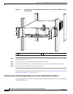
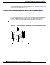
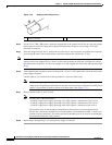
In the second configuration, for a telco-type rack, the rack-mount brackets are installed at the middle of
the chassis and the cable-management bracket is installed at the right front of the chassis. (See
Figure 7-23.) You must install both sets of brackets before you install the chassis in the rack.
Note The cable-management bracket must be installed on the right side of the chassis when viewed from the
front.
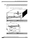
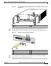
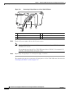
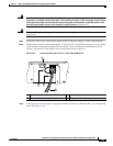
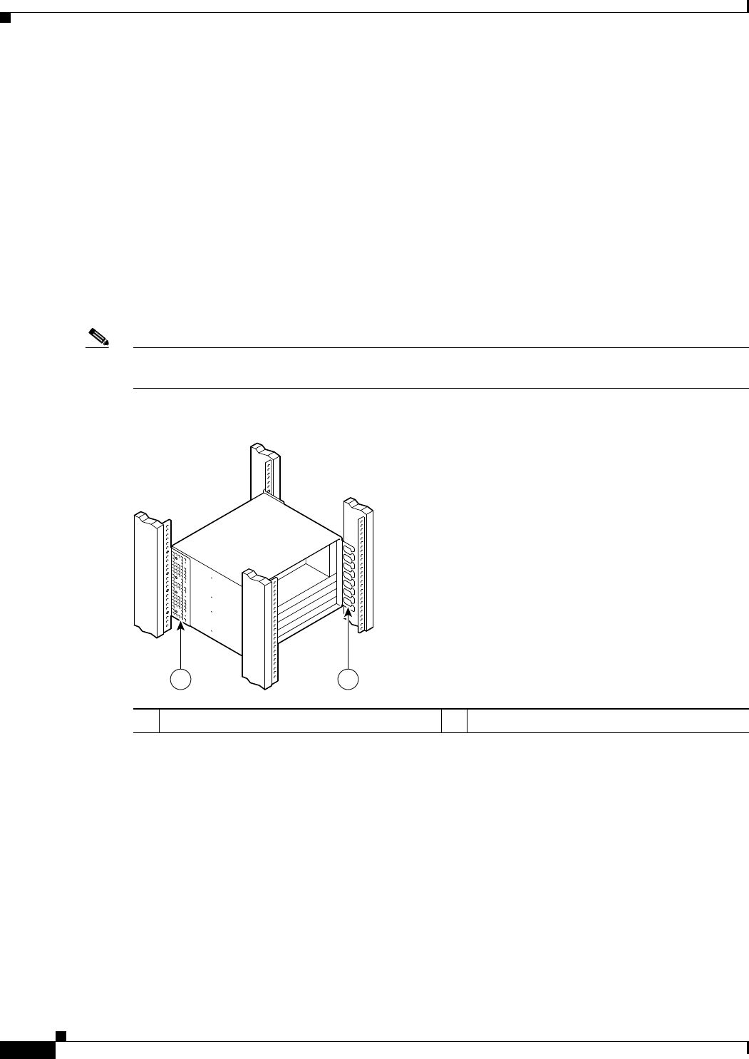
Figure 7-22 Installing the Chassis in a 4-Post Rack with an Installed Cable-Management Bracket
1 Rack-mount bracket 2 Cable-management bracket
93812
1 2