


6-5
Network Processing Engine and Network Services Engine Installation and Configuration
OL-4448-12
Chapter 6 NPE-G2 Overview
NPE-G2 Description and Overview
• The port numbering for the interfaces on the NPE-G2 starts with 0/1 and not with 0/0, as is typical
for other interface cards. This is to avoid conflicts with the Ethernet and Fast Ethernet ports on an
I/O controller, if it is also installed.
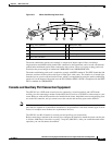
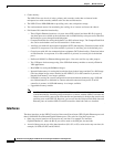
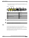
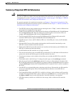
Figure 6-2 NPE-G2 Interfaces
Note The Fast Ethernet Management RJ-45 port is only used for management activities—not for any other
purpose.
Note The USB function is not supported on Cisco uBR7200 series routers.
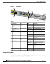
LEDs
This section provides information about the location and behavior of the NPE-G2 LEDs.
The NPE-G2 faceplate contains LEDs that indicate system and port status. The RJ-45 and SFP ports
share the same LINK ACTV LED because only one of these ports per interface (0/1, 0/2, or 0/3) can be
used at any one time. The EN (Enable) LED is on if the RJ-45 port is in use.
The PWR OK LED is on whether or not an I/O controller is present in the router. The CompactFlash
Disk slot can be used whether or not an I/O controller is present in the router. The SYST STAT LED
provides information about the status of the system.
1 CPU Reset 8 Console port
2 Fast Ethernet/Gigabit Ethernet RJ-45 port—GE 0/1 9 Auxiliary port
3 Gigabit Ethernet port—GE 0/1 10 Fast Ethernet Management
port—FE 0/2
4 Fast Ethernet/Gigabit Ethernet RJ-45 port—GE 0/2 11 USB port 0
5 Gigabit Ethernet port—GE 0/2 12 USB port 1
6 Fast Ethernet/Gigabit Ethernet RJ-45 port—GE 0/3 13 CompactFlash Disk slot
7 Gigabit Ethernet port—GE 0/3
CPU
RESET
NPE-G2
RJ45
GIGABIT ETHERNET 0 / 1
EN
LINK
ACTV
RJ45
GIGABIT ETHERNET 0 / 2
EN
LINK
ACTV
RJ45 CONSOLE AUX FE 0/2
FOR MANAGEMENT
USE ONLY
GIGABIT ETHERNET 0 / 2
EN
LINK
ACTV
USB
CF
ACTV
U
S
B
NETWORK PROCESSING ENGINE - G2
COMPACT FLASH
FE
LINK
PWR
OK
SYST
STAT
149062
2 4 6 8
31 5 7
10 11 13
9 12