


7-17
Network Processing Engine and Network Services Engine Installation and Configuration
OL-4448-12
Chapter 7 NPE-G1 and NPE-G2 Installation and Configuration Information
Removing the Network Processing Engine
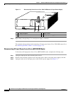
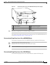
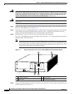
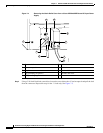
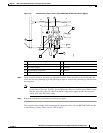
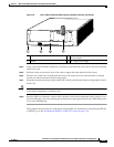
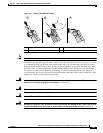
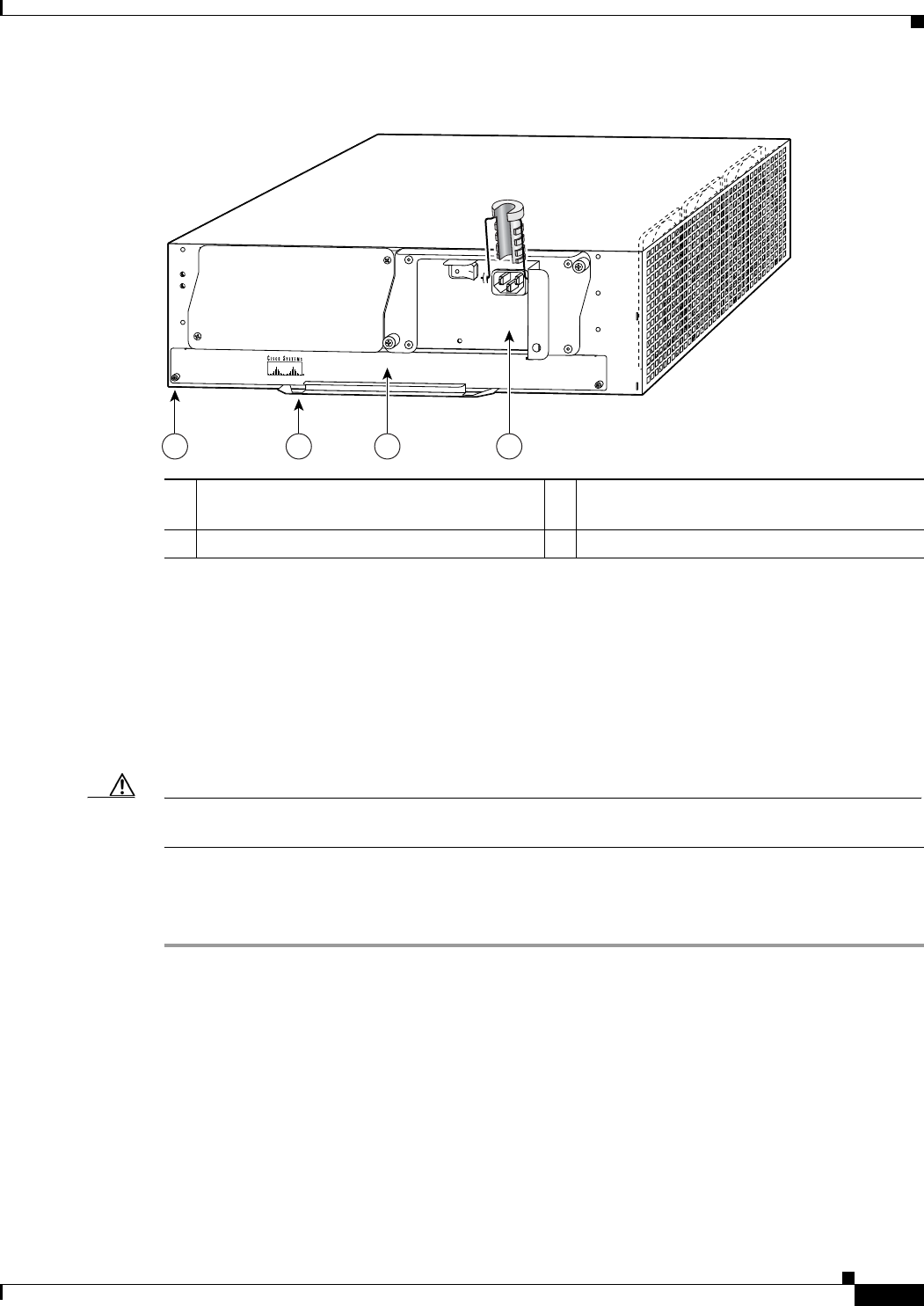
Figure 7-6 Cisco 7200 VXR Router NPE Captive Installation Screws and Handle
Step 4 Using a 3/16-inch flat-blade screwdriver, loosen the screws that secure the router to the front mounting
strips of the rack.
Step 5 Position at least one person in front of the rack to support the front underside of the router.
Step 6 From the rear of the rack, carefully push the front of the router out of the rack until there is enough
clearance to remove the network processing engine.
Step 7 Grasp the network processing engine handle and carefully pull the network processing engine from its
chassis slot.
Caution Handle the network processing engine by the carrier edges and handle only; never touch the printed
circuit board components or connector pins.
Step 8 Place the NPE on an antistatic surface with its printed circuit board components facing upward, or in a
static shielding bag. If you are returning the network processing engine to the factory, immediately place
it in a static shielding bag.
This completes the procedure for removing an installed NPE. For instructions on installing the NPE-G1
or NPE-G2, go to the
“Installing the NPE-G1 or NPE-G2” section on page 7-18.
1 Captive installation screw 3 Network processing engine or network
services engine
2 Handle 4 AC-input power supply
66605
NETWORK PROCESSING ENGINE-300
1 2 3 4