


7-30
Network Processing Engine and Network Services Engine Installation and Configuration
OL-4448-12
Chapter 7 NPE-G1 and NPE-G2 Installation and Configuration Information
Installing the NPE-G1 or NPE-G2
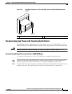
Note Do not use the cable-management bracket as a handle for inserting and removing the NPE-G1 or
NPE-G2 in the chassis. You must always first unfasten the NPE-G1 or NPE-G2 captive installation
screws and remove the cable-management bracket before removing or inserting the NPE-G1 or NPE-G2
in the chassis.
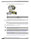
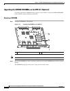
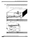
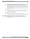
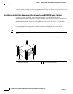
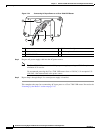
Figure 7-17 Installing the NPE-G1 or NPE-G2 Cable-Management Bracket
.
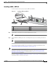
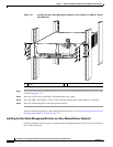
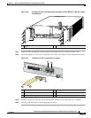
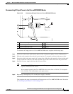
Figure 7-18 Installing the Cisco uBR7200-NPE-G1 or Cisco uBR7200-NPE-G2 Cable-Management
Bracket
.
1 Captive installation screw 2 Captive installation screw
NETWORK PROCESSING ENGINE-300
G
IG
ABIT ETHERNET 0/1
RJ45
GBIC
EN
RX
TX
LINK
C
O
N
S
O
LE
A
U
X
G
IGABIT ETH
ER
NET 0/1
RJ45
GBIC
EN
RX TX
LINK
G
IGABIT E
THERN
ET 0/1
RJ45
GBIC
EN
RX
TX
LINK
CPU
RESET
COMPACT FLASH
POWER
OK
SLOT
ACTIVE
NETW
OR
K PR
OCESSING EN
GINE - G
1
80680
2
1
1 Captive installation screw 2 Captive installation screw
82702
COMPACT FLASH
G
IGA
BIT E
THERNE
T 0/1
RJ45 GBIC
EN
RX
TX
LINK
C
O
N
SO
L
E
A
U
X
GIG
ABIT ETHERNE
T 0/1
RJ45
GBIC
EN
RX
TX
LINK
G
IG
A
BIT E
THE
RNET 0/1
RJ45
GBIC
EN
RX
TX
LINK
CPU
RESET
POWER
ON
SLOT
ACTIVE
N
E
T
W
O
R
K
P
R
O
C
E
S
S
IN
G
E
N
G
IN
E
- G
1
2
1