


6-14
Network Processing Engine and Network Services Engine Installation and Configuration
OL-4448-12
Chapter 6 NPE-G2 Overview
NPE-G2 Memory Information and Specifications
Note With reference to the RJ-45 pinout in Table 6-7, proper common-mode line terminations should be used
for the unused Category 5 UTP cable pairs 4/5 and 7/8. Common-mode termination reduces
electromagnetic interference (EMI).
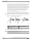
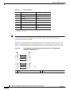
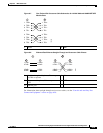
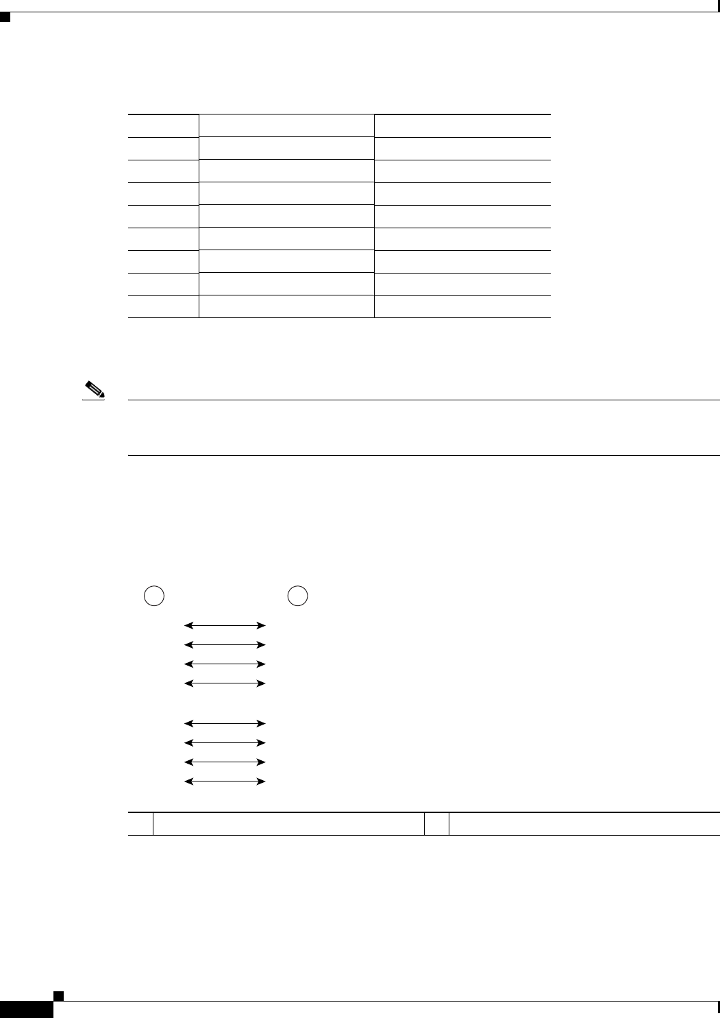
Depending on your RJ-45 interface cabling requirements, use the pinouts shown in Figure 6-6 and
Figure 6-7 for Gigabit Ethernet straight-through and crossover twisted-pair cable connections. Use
Figure 6-8 for Ethernet/Fast Ethernet straight-through and crossover twisted-pair cable connections.
Figure 6-6 Four Twisted-Pair Straight-Through Cable Schematics for 10/100/1000 and
1000BASET SFP Module Ports
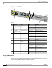
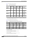
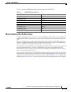
Ta ble 6-7 RJ-45 Port Pinouts
Pin 10/100 Signal Gigabit Ethernet Signal
1 Tx Data+
1
1. Tx Data = Transmit Data
Tx A+
2 Tx Data– Tx A–
3 Rx Data+
2
2. Rx Data = Receive Data
Rx B+
4 N/C Tx C+
5 N/C Tx C–
6 Rx Data– Rx B–
7 N/C Rx D+
8 NC Rx D–
1 Router 2 Hub
1 2
1 TPO+
2 TPO-
3 TP1+
6 TP1-
1 TP1+
2 TP1-
3 TPO+
6 TPO-
4 TP2+
5 TP2-
7 TP3+
8 TP3-
4 TP3+
5 TP3-
7 TP2+
8 TP2-
129086