


7-45
Network Processing Engine and Network Services Engine Installation and Configuration
OL-4448-12
Chapter 7 NPE-G1 and NPE-G2 Installation and Configuration Information
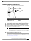
Installing the NPE-G1 or NPE-G2
Powering Up the Router
To power up a Cisco 7200 VXR router, Cisco uBR7246VXR router, or Cisco uBR7225VXR router that
has an installed power supply, complete the following steps:
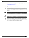
Step 1 Check for the following:
–
Each port adapter is inserted in its slot, and its respective port adapter lever is in the locked
position.
–
The network processing engine and the I/O controller or I/O controller blank panel are inserted
in their respective slots, and the captive installation screws are tightened.
–
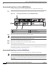
All network interface cables are connected to the port adapters or I/O controller or NPE-G1 or
NPE-G2 interfaces.
–
Each cable interface line card is inserted in its slot, and its respective captive installation screws
are tightened (Cisco
uBR7246VXR router only).
–
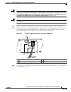
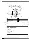
(Optional) A CompactFlash Disk is installed in the CompactFlash Disk slot in the NPE-G1 or
NPE-G2. If you also have an I/O controller installed, you can optionally install a PC Card or
Flash Disk in one of the I/O controller’s PC Card slots.
Note A Flash Disk can be installed in either slot 0 or slot 1 of the I/O controller. A
CompactFlash Disk can be installed only in the CompactFlash Disk slot in the NPE-G1
or NPE-G2.
–
(Optional) A USB Flash memory module or USB eToken Pro key is inserted into a USB port on
the NPE-G2.
–
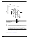
Each AC-input power cable is connected and secured with the cable-retention clip, except for
uBR7224VXR routers(AC-input power supplies only).
–
For a Cisco 7200 VXR router, each DC lead is connected and secured to the power supply
faceplate with a cable tie.
–
For a Cisco uBR7246VXR router, each DC lead is connected with M4 nuts for the grounding
receptacle and the strain-relief cover over the +V and –V leads (DC-input power supplies only).
–
Each DC lead is connected and secured to the power source (DC-input power supplies only).
–
Ensure that the tape (that you applied earlier) is removed from the circuit breaker switch handle,
and power is restored by moving the circuit breaker handle to the on (|) position (DC-input
power supplies only).
–
The console terminal is turned on.
Caution When the power switch on a Cisco uBR7200 series power supply is turned to the off (O) position, the
power supply enters a reset cycle for 90 seconds. Wait at least 90 seconds before turning the power
switch back to the on (|) position. If you do not wait the full 90 seconds, the power supply does not
restart.
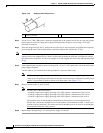
Step 2 At the rear of the router, place the power switch on the power supply in the on (|) position. Repeat this
step if a second power supply is installed in the router. The green OK LED on the power supply turns on.