


9-31
Network Processing Engine and Network Services Engine Installation and Configuration
OL-4448-12
Chapter 9 Removing and Installing the NPE or NSE
Removing and Replacing the NPE or NSE
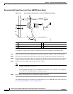
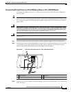
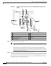
Step 4 Connect the two-hole grounding lug on the grounding lead to the M5 grounding receptacles with the M5
nuts. Tighten the nuts using an 8-mm wrench or nut driver (or adjustable wrench). (See
Figure 9-24.)
Step 5 Insert the stripped end of the +V lead all the way into the +V lead receptacle and tighten the receptacle
screw using the 3/16-inch flat-blade screwdriver. Repeat this step for the –V lead.
Note Make sure that the entire stripped end of each lead is inserted all the way into its receptacle. If any
exposed wire at the stripped end of a lead is visible after inserting the lead into its receptacle, remove
the lead from the receptacle, use the wire stripper to cut the stripped end of the lead, and repeat through
Step 5.
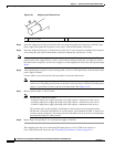
Step 6 After tightening the receptacle screw or nuts for the ground, +V, and –V DC-input leads, secure the leads
to the power supply faceplate.
Step 7 Run the +V and –V leads between the two strain-relief studs on the power supply faceplate.
Note A service loop is not required in the lead attached to the grounding lug because this lead is
separate from the +V and –V leads and is secured by two M5 nuts to the M5 receptacles.
Step 8 Replace the strain-relief cover over the +V and –V leads and secure the cover to the strain-relief studs
with the two M4 nuts using the 7-mm wrench or nut driver (or adjustable wrench).