


9-20
Network Processing Engine and Network Services Engine Installation and Configuration
OL-4448-12
Chapter 9 Removing and Installing the NPE or NSE
Removing and Replacing the NPE or NSE
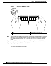
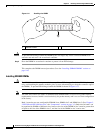
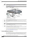
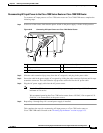
Caution SODIMMs are sensitive components that are susceptible to ESD damage. Handle SODIMMs by the
edges only; avoid touching the memory modules, pins, or traces (the metal fingers along the connector
edge of the SODIMM). (See Figure 9-15.)
Figure 9-15 Handling a SODIMM
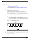
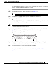
Follow these steps to install the new SODIMM:
Step 1 Remove a new SODIMM from the antistatic container.
Step 2 Hold the SODIMM component-side-up, with the connector edge (the metal fingers) away from you.
Step 3 Tilt the SODIMM to approximately the same angle as the socket, and insert the connector edge into the
socket.
Caution When inserting the SODIMM, use firm but not excessive pressure. If you damage a socket, you will have
to return the NPE-400 to the factory for repair.
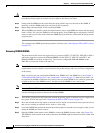
Step 4 Gently press on the SODIMM until the SODIMM spring latches snap into place.
Step 5 If the SODIMM appears misaligned, carefully remove it and reseat it in the socket. Push the SODIMM
gently back into the socket until the spring latches snap into place.
This completes the SDRAM SODIMM replacement procedure. To reinstall the NPE-400 in the chassis,
see the
“Installing the NPE or NSE” section on page 9-21.
Checking a SDRAM Upgrade or Replacement
If, after a SDRAM upgrade or replacement, the system fails to boot properly, or if the console terminal
displays a checksum or memory error, ensure that the SIMM, DIMM, or SODIMM is installed correctly.
If necessary, shut down the system and remove the network processing engine or network services
engine. Check the SIMM, DIMM, or SODIMM by looking straight down it and then at eye level. The
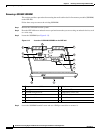
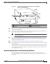
ETHERNET 10 BASE T
TO HUB
TO PC
+5, -24, -71, VDC
1
2
3
4
CONSOLE
Model Cisco 813
ISDN S/T
PHONE
1
2
ISDN U
ISDN U
NOR
RVS
ON
OFF
DSU
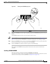
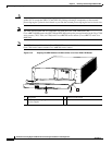
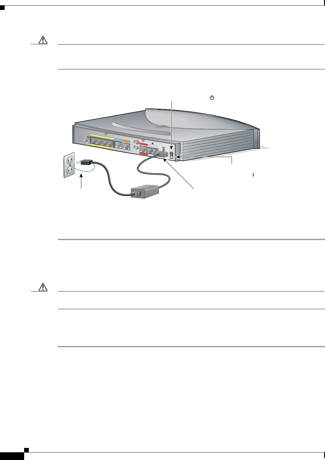
4. Connect ground
conductor to
grounding terminal
and power cord
plug to electrical outlet.
3. Connect power cord
to power supply.
2. Connect power
supply cable.
5. Press power
switch to on ( ).
1. Press power switch to standby ( ).
Cisco 813 router
33105
Desktop power
supply