


5-19
Network Processing Engine and Network Services Engine Installation and Configuration
OL-4448-12
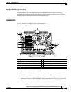
Chapter 5 NPE-G1 Overview
Connection Equipment and Specifications
The Cisco 7200 series routers ship with a roll-over cable. Connection to a terminal or a modem requires
an RJ-45-to-DB-25 adapter, and possibly a DB-25-to-DB9 adapter. Refer to
Table 5-10 for the cable and
adapter configurations that can be used to connect terminals and modems to the Cisco 7200 series
routers.
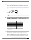
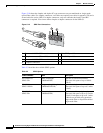
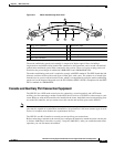
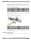
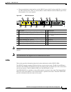
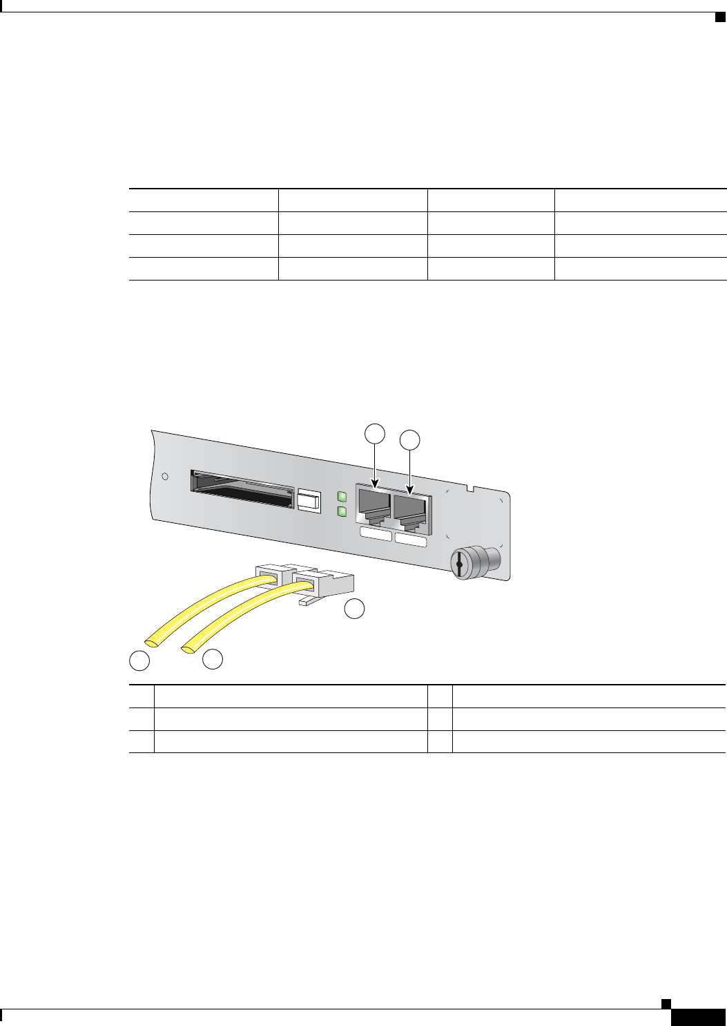
The cable and auxiliary ports are configured as asynchronous serial ports. Figure 5-13 shows the RJ-45
console and auxiliary port connections.
Figure 5-13 Console and Auxiliary Port RJ-45 Connections
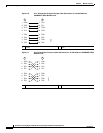
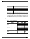
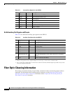
A cable and adapter kit is available from Cisco (Product Number ACS-2500ASYN=). Table 5-10
describes the cable and adapter configurations that can be used to connect terminals and modems to the
console or the auxiliary port.
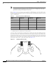
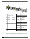
RJ-45 Console Port Signals and Pinouts
The NPE-G1 console port supports Data Carrier Detect (DCD). Table 5-11 lists the RJ-45 console port
signals for the NPE-G1.
Ta ble 5-10 Asynchronous Device Cabling Options
Access Server Port RJ-45 Cable Type DB-25 Adapter End Device
Console or auxiliary Roll-over FDTE
1
1. The FDTE RJ-45-to-DB-25 adapter is labeled “Terminal”.
Terminal
Console or auxiliary Straight FDCE Terminal
Auxiliary or console Roll-over MMOD
2
2. The MMOD RJ-45-to-DB-25 adapter is labeled “Modem”.
Modem
1 Console port 4 Cable to console terminal or DTE
2 Auxiliary port 5 Cable to modem or DCE
3 RJ-45 connectors
CONSOLE
AUX
CPU
RESET
COMPACT FLASH
POWER
ON
SLOT
ACTIVE
NETWORK PROCESSING ENGINE - G1
66777
1
2
3
4
5