


7-38
Network Processing Engine and Network Services Engine Installation and Configuration
OL-4448-12
Chapter 7 NPE-G1 and NPE-G2 Installation and Configuration Information
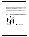
Installing the NPE-G1 or NPE-G2
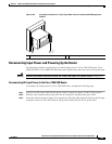
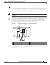
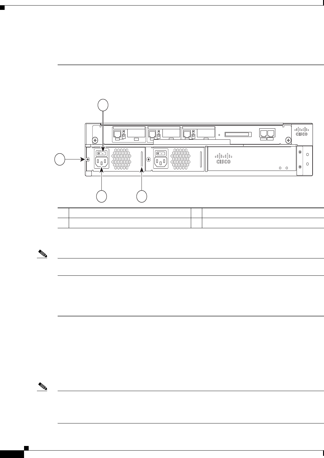
Reconnecting AC-Input Power to the Cisco uBR7225VXR Router
To connect AC-input power to the Cisco uBR7225VXR router, complete the following steps:
Step 1 At the rear of the router, ensure that the power switch on the power supply is in the off position.
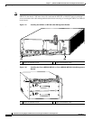
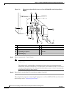
Figure 7-26 Connecting AC-Input Power to a Cisco UBR7225VXR Router
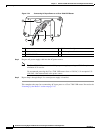
Step 2 Plug the power cable into the AC connector of the power supply.
Note For additional AC power cable strain relief, secure the cable to the power supply handle by inserting a
nylon cable tie through the hole in the handle and around the cable.
Step 3 Plug the AC power supply cable into the AC power source.
Step 4 Repeat Step 1 through Step 3 for the second power supply, if required.
Step 5 Turn on the power switch on the router.
This completes the steps for reconnecting AC-Input power to a Cisco UBR7225VXR router. Proceed to
the
“Powering Up the Router” section on page 7-45
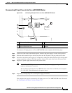
Reconnecting DC-Input Power to the Cisco 7200 VXR Router
To reconnect DC-input power to a Cisco 7200 VXR router, complete the following steps.
Note The color coding of the DC-input power supply leads depends on the color coding of the DC power
source at your site. Typically, green or green and yellow are used for ground. Make certain that the lead
color coding you choose for the DC-input power supply matches the lead color coding used at the DC
power source.
1
Power switch
4
AC-input receptacle
2
Handle
5
Captive installation screw
270538
uBR7225-VXR
uBR7225-VXR
1
23
4