


7-39
Network Processing Engine and Network Services Engine Installation and Configuration
OL-4448-12
Chapter 7 NPE-G1 and NPE-G2 Installation and Configuration Information
Installing the NPE-G1 or NPE-G2
Warning
Before completing any of the following steps, and to prevent short-circuit or shock hazards, ensure
that power is removed from the DC circuit. To ensure that all power is OFF, locate the circuit breaker
on the panel board that services the DC circuit, switch the circuit breaker to the OFF position, and
tape the switch handle of the circuit breaker in the OFF position.
Statement 322
Warning
When installing the unit, the ground connection must always be made first and disconnected last.
Statement 42
Step 1 At the rear of the router, check that the power switch on the power supply is in the off (O) position.
Step 2 Ensure that no current is running through the –V and +V leads. To ensure that all power is off, locate the
circuit breaker on the panel board that services the DC circuit, switch the circuit breaker to the off
position, and tape the switch handle of the circuit breaker in the off position.
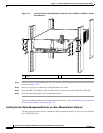
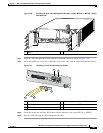
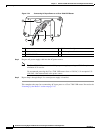
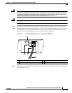
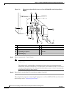
Figure 7-27 Connecting DC-Input Power to a Cisco 7200 VXR Router
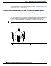
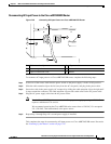
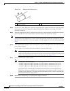
Step 3 If necessary, use a wire stripper to strip approximately 0.55 inch (14 mm) from the –V, +V, and ground
leads. (See
Figure 7-28.)
1 Power switch 3 Cable tie
2 Ground lead service loop 4 DC power leads
66432
2
1
3
4