


7-22
Network Processing Engine and Network Services Engine Installation and Configuration
OL-4448-12
Chapter 7 NPE-G1 and NPE-G2 Installation and Configuration Information
Installing the NPE-G1 or NPE-G2
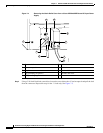
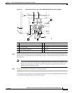
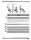
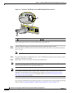
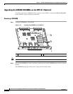
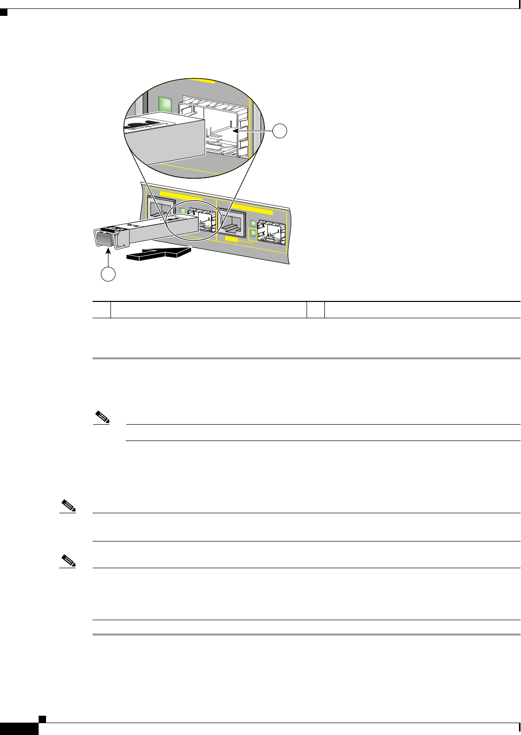
Figure 7-10 Inserting an SFP Module into the NPE-G2 Gigabit Ethernet Port 0/1
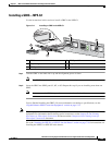
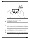
Use the following procedure to install an SFP module in the NPE-G2:
Step 1 Attach an ESD-preventive wrist strap between you and an unpainted chassis surface.
Step 2 Locate the label on the SFP module and turn the SFP module so the label is on top and the alignment
groove is down.
Note The SFP module is keyed so that it cannot be inserted incorrectly.
Step 3 Insert the SFP module into SFP port 0/1, 0/2, or 0/3. The SFP module snaps into place when you have
completely and properly inserted it.
Step 4 Repeat Step 2 if you are inserting a second or third SFP module.
Note Do not remove the plug from the SFP module optical bores until you are ready to install the network
interface optical fiber cable. Save the plug for future use.
Note We strongly recommend cleaning all optical fiber connections before connecting optical cables to
equipment. For information about cleaning optical connectors, see the
Inspection and Cleaning
Procedures for Fiber-Optic Connections document and the Compressed Air Cleaning Issues for
Fiber-Optic Connections document.
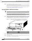
This completes the SFP module installation procedure. For information on inserting the NPE-G2 into the
chassis, see the
“Inserting the NPE-G1 or NPE-G2 into the Router” section on page 7-28.
1 SFP port 0/1 2 SFP module
RJ45
GIGABIT ETHERNET 0 / 1
EN
LINK
ACTV
RJ45
GIGABIT ETHERNET 0 / 2
EN
LINK
ACTV
149065
TX
RX
EN
LINK
ACTV
2
1