


7-42
Network Processing Engine and Network Services Engine Installation and Configuration
OL-4448-12
Chapter 7 NPE-G1 and NPE-G2 Installation and Configuration Information
Installing the NPE-G1 or NPE-G2
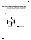
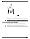
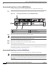
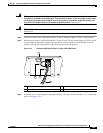
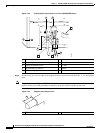
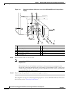
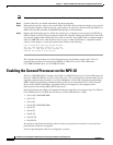
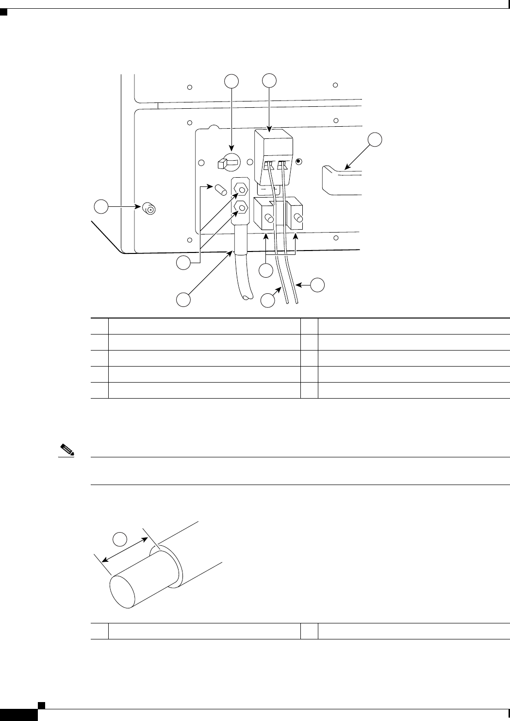
Figure 7-29 Connecting DC-Input Power to a Cisco uBR7246VXR Router
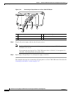
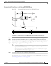
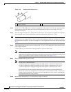
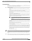
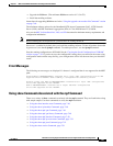
Step 3 SIf necessary, use a wire stripper to strip approximately 0.55 inch (14 mm) from the –V, +V, and ground
leads.
Note The ground lead for the Cisco uBR7200 series DC-input power supply consists of a two-hole grounding
lug that connects to an M5 grounding receptacle; you do not need to strip this ground lead.
Figure 7-30 Stripping the DC-Input Lines
1 Power switch 6 –V lead
2 Power receptacle 7 M4 studs
3 Captive installation screw 8 +V lead
4 M5 grounding receptacles 9 Handle
5 M5 grounding lug
66407
3
8
1
2
9
7
5
6
4
1 0.55 in. (14 mm)
57019
1