


9-21
Network Processing Engine and Network Services Engine Installation and Configuration
OL-4448-12
Chapter 9 Removing and Installing the NPE or NSE
Removing and Replacing the NPE or NSE
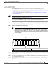
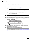
SIMMs or DIMMs should be aligned at the same angle and the same height as others on the board when
properly installed. If the SIMM, DIMM, or SODIMM appears to stick out or rest in the socket at an odd
angle, remove it and reinsert it. Then replace the network processing engine or network services engine
and reboot the system for another installation check.
If after several attempts the system fails to restart properly, contact a service representative for
assistance. Before you call, note any error messages, unusual LED states, or other indications that might
help solve the problem.
Installing the NPE or NSE
Note If you have difficulty installing a network processing engine or I/O controller in the lowest slot of a
Cisco 7200 VXR router that is rack-mounted, remove the port adapters, network processing engine and
I/O controller from the chassis and reinstall them. Install the network processing engine and I/O
controller in the lowest slots first, then populate the slots above them, in a bottom-to-top order.
To install an NPE or NSE in the router, complete the following steps:
Note When installing an NPE-175, NPE-225, NPE-300, NPE-400, or NSE-1 in a Cisco 7200 VXR router that
is using a previously purchased I/O controller, you must upgrade the I/O controller boot helper image.
Instructions for upgrading the boot helper image on the I/O controller are contained in the online
Memory Replacement Instructions for the Network Processing Engine or Network Services Engine and
Input/Output Controller publication.
Step 1 Ensure that the router is powered down and the input power cable is disconnected from the router and
the power source. See the
“Powering Down the Router and Disconnecting Input Power” section on
page 9-2.
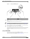
Step 2 Attach an ESD-preventive wrist strap between you and an unfinished chassis surface.
Step 3 Remove the new network processing engine or network services engine from its static shielding bag.
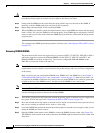
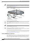
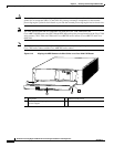
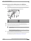
Step 4 Using both hands, grasp the NPE or NSE by its metal carrier edges and orient it so that its printed circuit
board components are upward. (See
Figure 9-16.)
Caution Handle the network processing engine or network services engine by the carrier edges and handle only;
never touch the printed circuit board components or connector pins.
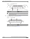
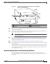
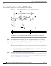
Step 5 Align the left and right edges of the network processing engine or network services engine printed circuit
board between the network processing engine slot guides.
Note For the NPE-175 and NPE-225, align the left and right edges of the network processing engine
metal carrier into the guides.