


Therefore, you want to ensure that both HSG80 controllers
start at the same time under all circumstances so that the
controller sees its own preferred units.
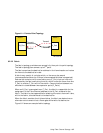
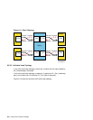
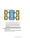
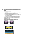
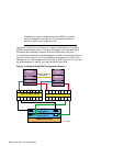
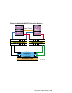
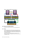
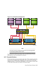
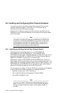
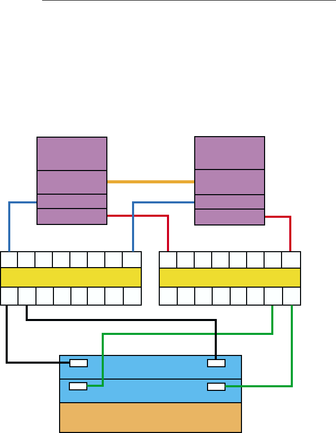
Figure 6–5, Figure 6–6, and Figure 6–7 show three different multiple-bus
NSPOF cluster configurations. The only difference is the fiber-optic cable
connection path between the switch and the HSG80 controller ports.
If you consider the loss of a host bus adapter or switch, the configurations in
Figure 6–6 and Figure 6–7 will provide better throughput than Figure 6–5
because you still have access to both controllers. With Figure 6–5, if you lose
a host bus adapter or switch, you lose the use of a controller.
Figure 6–5: Multiple-Bus NSPOF Configuration Number 1
ZK-1706U-AI
KGPSA
Member
System
2
KGPSA
Memory
Channel
KGPSA
Member
System
1
KGPSA
Memory
Channel
Memory Channel
Interface
Fibre Channel SwitchFibre Channel Switch
HSG 80
Controller A
HSG 80
Controller B
RA8000/ESA12000
Port 1
Port 2
Port 1 Port 2
6–12 Using Fibre Channel Storage