


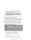
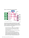
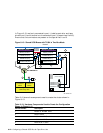
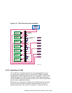
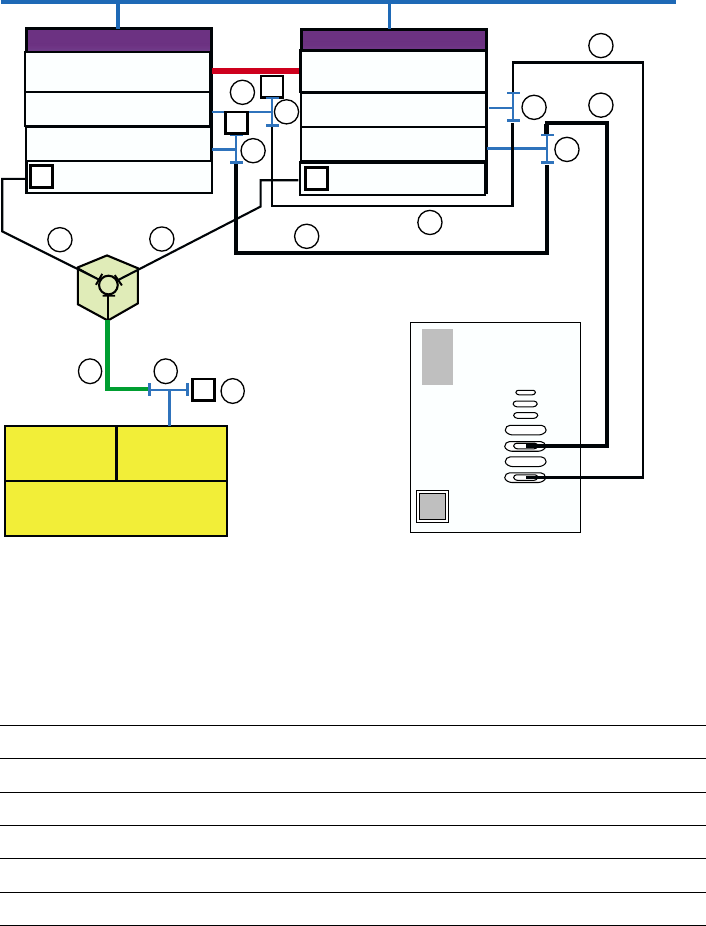
In Figure 8–13, one bus is connected to port 1 (robotics controller and tape
drives 0 and 1) and the other bus is connected to port 3 (tape drives 2 and 3).
Ensure that the terminators are present on the tape drives 1 and 3.
Figure 8–13: Shared SCSI Buses with TL894 in Two-Bus Mode
KZPBA-CB (ID 7)
Memory
Channel
Interface
Memory Channel
KZPBA-CB (ID 6)
Member System 1
DS-DWZZH-03
T
T
T
2
1
4
1
3
StorageWorks
RAID Array 7000
HSZ70HSZ70
Controller B Controller A
T
KZPBA-CB (ID 7)
5
5
6
7
7
KZPBA-CB (ID 6)
T
T
Network
T
Member System 2
Memory Channel
KZPBA-CB (ID 6)
KZPBA-CB (ID 7)
T
5
TL894
SCSI Port 4
SCSI Port 3
SCSI Port 2
SCSI Port 1
(2-bus mode)
5
7
7
ZK-1625U-AI
Table 8–10 shows the components used to create the cluster shown in
Figure 8–13.
Table 8–10: Hardware Components Used to Create the Configuration
Shown in Figure 8–12
Callout Number
Description
1
BN38C or BN38D cable
a
2
BN37A cable
b
3
H8861-AA VHDCI trilink connector
4
H8863-AA VHDCI terminator
5
BN21W-0B Y cable
8–42 Configuring a Shared SCSI Bus for Tape Drive Use