


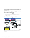
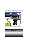

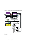

8.8.2.1 Cabling the DLT MiniLibraries
You must make the following connections to render the DLT MiniLibrary
system operational:
• Expansion unit to the motor mechanism: The motor mechanism cable is
about 1 meter long and has a DB-15 connector on each end. Connect it
between the connector labeled Motor on the expansion unit to the motor
on the pass-through mechanism.
_____________________ Note _____________________
This cable is not shown in Figure 8–11 as the pass-through
mechanism is not shown in the figure.
• Robotics control cables from each base module to the expansion unit:
These cables have a DB-9 male connector on one end and a DB-9 female
connector on the other end. Connect the male end to the Expansion
Unit Interface connector on the base module and the female end to any
Expansion Modules connector on the expansion unit.
_____________________ Note _____________________
It does not matter which interface connector a base module
is connected to.
• SCSI bus connection to the expansion unit robotics: Connect the shared
SCSI bus that will control the robotics to one of the SCSI connectors
on the expansion unit with a BN21K (or BN21L) cable. Terminate the
SCSI bus with an H879-AA terminator on the other expansion unit
SCSI connector.
• SCSI bus connection to each of the base module tape drives: Connect a
shared SCSI bus to one of the DLT1 or DLT2 SCSI connectors on each of
the base modules with BN21K (or BN21L) cables. Terminate the other
DLT1 or DLT2 SCSI bus connection with an H879-AA terminator.
You can daisy chain between DLT1 and DLT2 (if present) with a
0.3-meter SCSI bus jumper (supplied with the TL891). Terminate the
SCSI bus at the tape drive on the end of the shared SCSI bus with an
H879-AA terminator.
8–30 Configuring a Shared SCSI Bus for Tape Drive Use