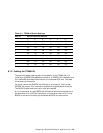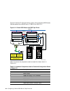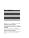
Table 8–2: Hardware Components Used to Create the Configuration Shown
in Figure 8–2 (cont.)
Callout Number
Description
8
DWZZA-VA with H885-AA trilink connector
9
DWZZB-VW with H885-AA trilink connector
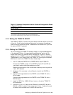
a
The maximum length of the BN38C (or BN38D) cable on one SCSI bus segment must not exceed 25 meters.
b
The maximum length of the BN37A cable must not exceed 25 meters.
c
The maximum combined length of these cables must not exceed 25 meters.
8.1.3 Setting the TZ88N-TA SCSI ID
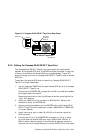
The TZ88N-TA SCSI ID is set with a push-button counter switch on the rear
of the unit. Push the button above the counter to increment the address;
push the button below the counter to decrement the address until you have
the desired SCSI ID selected.
8.1.4 Cabling the TZ88N-TA
You must connect the TZ88N-TA tabletop model to a single-ended segment
of the shared SCSI bus. It is connected to a differential portion of the
shared SCSI bus with a DWZZA-AA or DWZZB-AA. Figure 8–7 shows a
configuration of a TZ885 for use on a shared SCSI bus. You can replace the
TZ885 shown in the illustration with a TZ88N-TA. To configure the shared
SCSI bus for use with a TZ88N-TA, follow these steps:
1. You will need one DWZZA-AA or DWZZB-AA for each TZ88N-TA.
Ensure that DWZZA jumper J2 or DWZZB jumpers W1 and W2 are
installed to enable the single-ended termination.
Remove the termination from the differential end by removing the five
14-pin SIP resistors.
2. Attach a trilink connector to the differential end of the DWZZA or
DWZZB.
3. Connect the single-ended end of a DWZZA to the TZ88N-TA with a
BC19J cable.
Connect the single-ended end of a DWZZB to the TZ88N-TA with a
BN21M cable.
4. Install a H8574-A or H8890-AA terminator on the other TZ88N-TA
SCSI connector.
5. Connect a trilink or Y cable to the differential shared SCSI bus with
BN21K or BN21L cables. Ensure that the trilink or Y cable at the end
of the bus is terminated with an H879-AA terminator.
Configuring a Shared SCSI Bus for Tape Drive Use 8–5


