


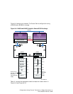

Later sections describe how to install cables to configure an HSZ20, HSZ40,
or HSZ50 in a TruCluster Server configuration with two member systems.
9.4.1 Preparing BA350, BA356, and UltraSCSI BA356 Storage Shelves
for an Externally Terminated TruCluster Server Configuration
You may be using the BA350, BA356, or UltraSCSI BA356 storage shelves in
your TruCluster Server configuration as follows:
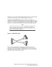
• A BA350 storage shelf provides access to SCSI devices through an
8-bit, single-ended, and narrow SCSI-2 interface. It can be used with a
DWZZA-VA and connected to a differential shared SCSI bus.
• A non-Ultra BA356 storage shelf provides access to SCSI devices
through a 16-bit, single-ended, and wide SCSI-2 interface. In a cluster
configuration, you would connect a non-Ultra BA356 to the shared SCSI
bus using DWZZB-VW.
• An UltraSCSI BA356 storage shelf provides access to UltraSCSI devices
through a 16-bit, single-ended, wide UltraSCSI interface. In a cluster
configuration, you would connect an UltraSCSI BA356 to the shared
SCSI bus through the DS-BA35X-DA personality module.
The following sections discuss the steps necessary to prepare the individual
storage shelves, and then connect two storage shelves together to provide
the additional storage.
______________________ Note _______________________
This material has been written with the premise that there are
only two member systems in any TruCluster Server configuration
using direct connect disks for storage. Using this assumption,
and further assuming that the member systems use SCSI IDs 6
and 7, the storage shelf housing disks in the range of SCSI IDs 0
through 6 can only use SCSI IDs 0 through 5.
If there are more than two member systems, additional disk slots
will be needed to provide the additional member system SCSI IDs.
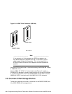
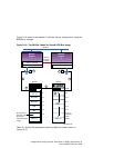
9.4.1.1 Preparing a BA350 Storage Shelf for Shared SCSI Usage
To prepare a BA350 storage shelf for usage on a shared SCSI bus, follow
these steps:
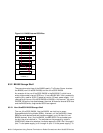
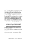
1. Ensure that the BA350 storage shelf’s internal termination and jumper
is installed (see Section 9.3.1 and Figure 9–6).
Configurations Using External Termination or Radial Connections to
Non-UltraSCSI Devices 9–15