


S1C88650 TECHNICAL MANUAL EPSON 93
5 PERIPHERAL CIRCUITS AND THEIR OPERATION (Programmable Timer)
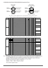
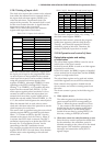
5.10.6 Setting of TOUT output
The 16-bit programmable timer can generate TOUT
signals with the underflow and compare match
signals of each timer. The TOUT signal generated in
the 16-bit programmable timer can be output from
the I/O port terminal shown in Table 5.10.6.1 so
that a clock is supplied for external devices or it can
be used as a PWM waveform output.
Table 5.10.6.1 TOUT output terminal
Timer
Timer 0
Timer 1
Timer 2
Timer 3
Output clock name
TOUT0
TOUT1
TOUT2
TOUT2
TOUT3
TOUT3
Output terminal
P14
P14
P15
P17
P15
P17
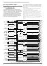
The TOUT signal rises at the falling edge of the
underflow signal and falls at the falling edge of the
_________
compare match signal. TOUT is the inverted TOUT
signal. Therefore, it is possible to change the
frequency and duty ratio of the TOUT signal by
setting the reload data register (RDR) and compare
data register (CDR).
However, it needs a condition setting: RDR > CDR,
CDR ≠ 0. In the case of RDR ≤ CDR, TOUT signal
is fixed at "1".
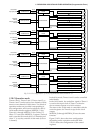
The TOUT output can be controlled ON and OFF
using the clock output control register PTOUTx of
_________
each timer and the TOUT output can be controlled
using the inverted clock output control register
RPTOUTx of Timer 2 or Timer 3.
When PTOUTx (RPTOUTx) is set to "1", the TOUTx
___________
(TOUTx) signal is output from the corresponding
port terminal, when "0" is set, the port is set for DC
output. When PTOUTx (RPTOUTx) is "1", settings
of the I/O control register IOC14/IOC15/IOC17
and data register P14D/P15D/P17D become
invalid.
Note: If PTOUT0 and PTOUT1 are set to "1" at the
same time, PTOUT1 is effective. Similarly, if
PTOUT2 (RPTOUT2) and PTOUT3
(RPTOUT3) are set to "1", PTOUT3
(RPTOUT3) is effective.
In the 16-bit mode, the output is controlled by the
control register PTOUT(H) for Timer(H). The clock
is output from Timer(H).
___________
Since the TOUTx (TOUTx) signal is generated
asynchronously from the register PTOUTx
(RPTOUTx), when the signal is turned ON or OFF
by the register settings, a hazard of a 1/2 cycle or
less is generated.
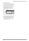
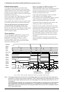
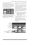
Figure 5.10.6.1 shows the output waveform of
TOUT signal.
Input clock
RDRx register
CDRx register
Down counter
Compare match signal
Underflow signal
TOUTx signal
PTOUTx/RPTOUTx
Output from TOUTx (P14/P15) terminal
Output from TOUTx (P17) terminal
7
6
70 6 5 4 3 2 1 0 7 6 5 4
CDR register value
3 2 1 0 7 6 5 4 3 2 1
RDR register value + 1
Fig. 5.10.6.1 Output waveform of TOUT signal