


140 EPSON S1C88650 TECHNICAL MANUAL
8 ELECTRICAL CHARACTERISTICS
8 ELECTRICAL CHARACTERISTICS
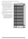
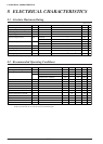
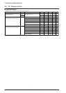
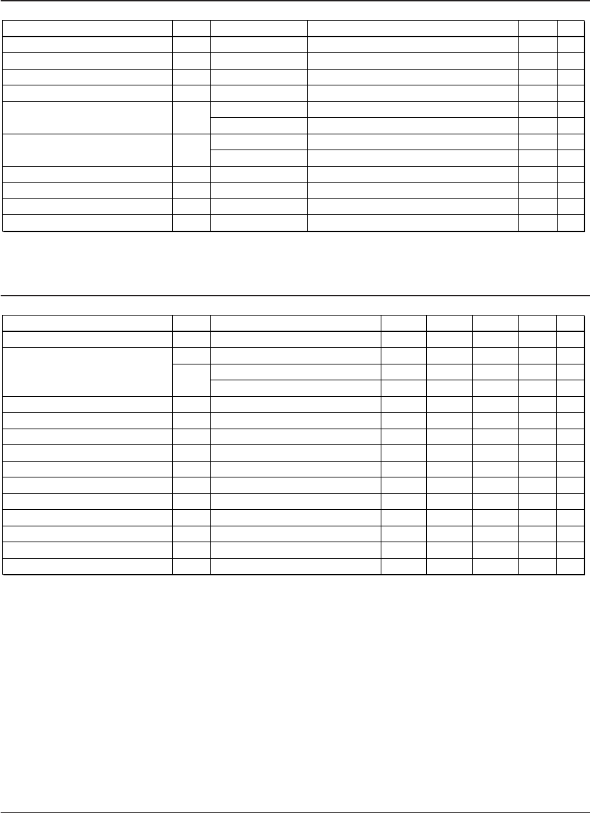
8.1 Absolute Maximum Rating
Item
Symbol
UnitRated value
Power voltage
Liquid crystal power voltage
Input voltage
Output voltage
High level output current
Low level output current
Permitted loss
Operating temperature
Storage temperature
Soldering temperature / time
V
DD
V
C5
V
I
V
O
I
OH
I
OL
P
D
Topr
Tstg
Tsol
V
V
V
V
mA
mA
mA
mA
mW
°C
°C
–
-0.3 to +4.7
-0.3 to +6.0
-0.3 to V
DD
+ 0.3
-0.3 to V
DD
+ 0.3
-5
-20
5
20
200
-20 to +70
-65 to +150
260°C, 10 sec
(
lead section
)
Note)
Note
1
Condition
1 terminal
Total of all terminals
1 terminal
Total of all terminals
1 In case of plastic package.
(V
SS
= 0 V)
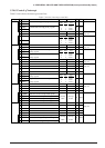
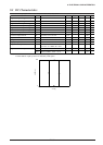
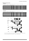
8.2 Recommended Operating Conditions
Item
Symbol
Min. Typ. Max. UnitCondition
Operating power voltage
Operating frequency
Capacitor between V
D1
and V
SS
Capacitor between V
C1
and V
SS
Capacitor between V
C2
and V
SS
Capacitor between V
C3
and V
SS
Capacitor between V
C4
and V
SS
Capacitor between V
C5
and V
SS
Capacitor between CA and CB
Capacitor between CA and CC
Capacitor between CD and CE
Capacitor between V
D2
and V
SS
Capacitor between CF and CG
V
DD
f
OSC1
f
OSC3
C
1
C
2
C
3
C
4
C
5
C
6
C
7
C
8
C
9
C
10
C
11
1.8
30
0.03
0.03
32.768
0.1
0.1
0.1
0.1
0.1
0.1
0.1
0.1
0.1
0.1
0.1
3.6
200
2.2
8.2
V
kHz
MHz
MHz
µF
µF
µF
µF
µF
µF
µF
µF
µF
µF
µF
CR oscillation
Crystal/ceramic oscillation
Note
1
1
1
1
1
1
1
1
1
1
Note) 1 When LCD drive power is not used, the capacitor is not necessary.
In this case, leave the V
C1
to V
C5
and CA to CG terminals open.