S1C88650 TECHNICAL MANUAL EPSON 109
5 PERIPHERAL CIRCUITS AND THEIR OPERATION (LCD Driver)
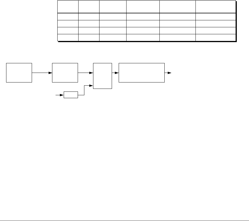
5.11.3 Frame frequency
This LCD driver allows selection of the source clock
for generating the frame signal from the OSC1
oscillation clock (fOSC1) and the programmable
timer 5 underflow signal. By using programmable
timer 5, flexible frame frequencies can be
programmed. Refer to Section 5.10.8, "Setting frame
frequency for LCD driver".
Use the LCD frame frequency source clock select
register FRMCS to select the source clock. When
FRMCS is set to "0", fOSC1 is selected, and when it is
set to "1", programmable timer 5 is selected. The
following shows the frame frequencies when fOSC1
is selected (fOSC1 = 32.768 kHz).
1/8 duty: 64 Hz
1/16 duty: 32 Hz
1/32 duty: 32 Hz
5.11.4 Switching drive duty
The S1C88650 supports three types of LCD drive
duty settings, 1/8, 1/16 and 1/32, and it can be
switched using the LDUTY0 and LDUTY1 registers.
Table 5.11.4.1 shows the relationship of the LDUTY
setting, drive duty and the maximum number of
displaying dots.
When 1/32 duty is selected, an LCD panel with 126
segments × 32 commons (maximum 4,032 dots) can
be driven.
When 1/16 duty is selected, an LCD panel with 126
segments × 16 commons (maximum 2,016 dots) can
be driven. The COM16–COM31 terminals become
invalid, in that they always output an OFF signal.
When 1/8 duty is selected, an LCD panel with 126
segments × 8 commons (maximum 1,008 dots) can
be driven. The COM8–COM31 terminals become
invalid, in that they always output an OFF signal.
The drive bias is 1/5 (five potentials, VC1, VC2, VC3,
VC4 and VC5) regardless of the drive duty selected.
The respective drive waveforms are shown in
Figures 5.11.4.1 to 5.11.4.3.
Table 5.11.4.1 Correspondence between drive duty and maximum number of displaying dots
LDUTY1
1
1
0
0
LDUTY0
1
0
1
0
Duty
Not allowed
1/16
1/32
1/8
Common
terminal
–
COM0–COM15
COM0–COM31
COM0–COM7
Segment
terminal
–
SEG0–SEG125
SEG0–SEG125
SEG0–SEG125
Maximum number
of display dots
–
2,016 dots
4,032 dots
1,008 dots
fOSC1 1/16
Frame
frequency
1/64 (1/32, 1/16 duty)
1/128 (1/8 duty)
Divider
Selector
1/2
Programmable timer 5
underflow signal
OSC1
oscillation
circuit
Fig. 5.11.3.1 Dividing the source clock to generate frame frequency


