


54 EPSON S1C88650 TECHNICAL MANUAL
5 PERIPHERAL CIRCUITS AND THEIR OPERATION (I/O Ports)
5.7 I/O Ports (P ports)
5.7.1 Configuration of I/O ports
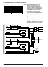
The S1C88650 is equipped with 16 bits of I/O ports
(P00–P07, P10–P17). The configuration of these I/O
ports will vary according to the bus mode as shown
below.
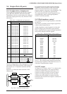
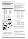
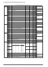
Table 5.7.1.1 Configuration of I/O ports
Terminal
P00
P01
P02
P03
P04
P05
P06
P07
P10
P11
P12
P13
P14
P15
P16
P17
I/O port P00
I/O port P01
I/O port P02
I/O port P03
I/O port P04
I/O port P05
I/O port P06
I/O port P07
Bus mode
ExpansionSingle chip
Data bus D0
Data bus D1
Data bus D2
Data bus D3
Data bus D4
Data bus D5
Data bus D6
Data bus D7
I/O port P10 (SIN)
I/O port P11 (SOUT)
I/O port P12 (SCLK)
I/O port P13 (SRDY)
I/O port P14 (TOUT0/TOUT1)
I/O port P15 (TOUT2/TOUT3)
I/O port P16 (FOUT)
I/O port P17 (TOUT2/TOUT3)
With respect to the data bus, see "5.2 System
Controller and Bus Control".
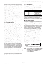
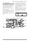
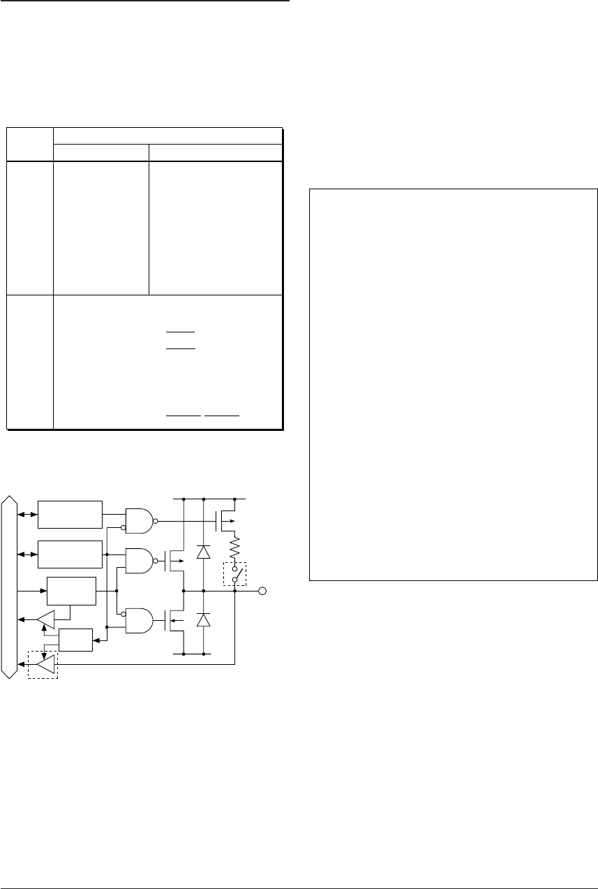
Figure 5.7.1.1 shows the structure of an I/O port.
V
DD
V
SS
Pxx
Pull-up control
register
Input
control
Data bus
Data
register
I/O control
register
*1
*2
*3
*1:
*2:
*3:
During output mode
During input mode
Schmitt input can be selected for P10–P17
by mask option.
Mask
option
Fig. 5.7.1.1 Structure of I/O port
I/O port can be set for input or output mode in one
bit unit. These settings are performed by writing
data to the I/O control registers.
I/O port terminals P10–P13 are shared with serial
interface input/output terminals and the function
of each terminal is switchable in software.
With respect to serial interface see "5.8 Serial
Interface".
The data registers and I/O control registers of I/O
ports set for data bus and serial interface output
terminals use are usable as general purpose
registers with read/write capabilities which do not
affect I/O activities of the terminal.
The same as above, the I/O control register of I/O
port set for serial interface input terminal use is
usable as general purpose register.
In addition to the general-purpose DC output,
special output can be selected for the I/O ports
P14–P17 with the software.
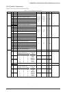
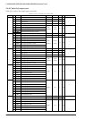
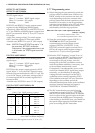
5.7.2 Mask option
I/O port pull-up resistors
P00 ............■■ With resistor ■■ Gate direct
P01 ............■■ With resistor ■■ Gate direct
P02 ............■■ With resistor ■■ Gate direct
P03 ............■■ With resistor ■■ Gate direct
P04 ............■■ With resistor ■■ Gate direct
P05 ............■■ With resistor ■■ Gate direct
P06 ............■■ With resistor ■■ Gate direct
P07 ............■■ With resistor ■■ Gate direct
P10 ............■■ With resistor ■■ Gate direct
P11 ............■■ With resistor ■■ Gate direct
P12 ............■■ With resistor ■■ Gate direct
P13 ............■■ With resistor ■■ Gate direct
P14 ............■■ With resistor ■■ Gate direct
P15 ............■■ With resistor ■■ Gate direct
P16 ............■■ With resistor ■■ Gate direct
P17 ............■■ With resistor ■■ Gate direct
I/O port input interface level
P10 ............■■ CMOS level ■■ CMOS Schmitt
P11 ............■■ CMOS level ■■ CMOS Schmitt
P12 ............■■ CMOS level ■■ CMOS Schmitt
P13 ............■■ CMOS level ■■ CMOS Schmitt
P14 ............■■ CMOS level ■■ CMOS Schmitt
P15 ............■■ CMOS level ■■ CMOS Schmitt
P16 ............■■ CMOS level ■■ CMOS Schmitt
P17 ............■■ CMOS level ■■ CMOS Schmitt
I/O ports P00–P07 and P10–P17 are equipped with
a pull-up resistor which goes ON in the input
mode. Whether this resistor is used or not can be
selected for each port (one bit unit). Furthermore,
the interface level for each port in P10–P17 can be
selected from CMOS level and CMOS Schmitt level.
5.7.3 I/O control registers and I/O mode
I/O ports P00–P07 and P10–P17 are set either to
input or output modes by writing data to the I/O
control registers IOC00–IOC07 and IOC10–IOC17
which correspond to each bit.
To set an I/O port to input mode, write "0" to the I/
O control register.
An I/O port which is set to input mode will shift to
a high impedance state and functions as an input
port.