S1C88650 TECHNICAL MANUAL EPSON 161
10 PAD LAYOUT
10 PAD LAYOUT
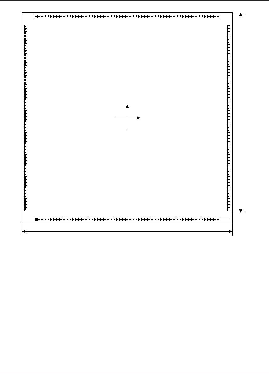
10.1 Diagram of Pad Layout
6.7 mm
Y
X
(0, 0)
6.7 mm
120 125 130 135 140 145 150 155 160 165 170 175
Die. No.
180
185
190
195
200
205
210
215
220
225
230
235
1510152025303540455055
60
65
70
75
115
110
105
100
95
90
80
85
Chip thickness: 400 µm
Pad opening: 90 µm
■ Pad 119 is used for the IC shipment test, so you should not bond it.


