


S1C88650 TECHNICAL MANUAL EPSON 5
1 INTRODUCTION
1.4 Mask Option
Mask options shown below are provided for the
S1C88650.
Several hardware specifications are prepared in
each mask option, and one of them can be selected
according to the application. Multiple specifications
are available in each option item as indicated in the
Option List.
Select the specifications that meet the target system
and check the appropriate box.
The option selection is done interactively on the
screen during function option generator winfog
execution, using this option list as reference. Mask
pattern of the IC is finally generated based on the
data created by the winfog. Refer to the
"S5U1C88000C Manual II" for details on the winfog.
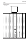
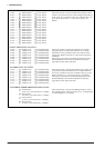
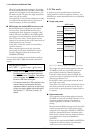
S1C88650 mask option list
The following shows the option list for generating the IC's mask pattern. Note that the Peripheral Circuit
Board installed in the ICE does not support some options.
1 OSC1 SYSTEM CLOCK
■■ 1. Crystal
■■ 2. CR
2 OSC3 SYSTEM CLOCK
■■ 1. Crystal
■■ 2. Ceramic
■■ 3. CR
3 MULTIPLE KEY ENTRY RESET
• Combination ..■■ 1. Not Use
■■ 2. Use K00, K01
■■ 3. Use K00, K01, K02
■■ 4. Use K00, K01, K02, K03
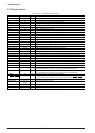
4 INPUT PORT PULL UP RESISTOR
• K00...................■■ 1. With Resistor ■■ 2. Gate Direct
• K01...................■■ 1. With Resistor ■■ 2. Gate Direct
• K02...................■■ 1. With Resistor ■■ 2. Gate Direct
• K03...................■■ 1. With Resistor ■■ 2. Gate Direct
• K04...................■■ 1. With Resistor ■■ 2. Gate Direct
• K05...................■■ 1. With Resistor ■■ 2. Gate Direct
• K06...................■■ 1. With Resistor ■■ 2. Gate Direct
• K07...................■■ 1. With Resistor ■■ 2. Gate Direct
______
• MCU/MPU ....■■ 1. With Resistor ■■ 2. Gate Direct
________
• RESET .............■■ 1. With Resistor ■■ 2. Gate Direct
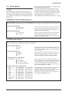
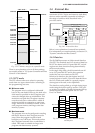
PERIPHERAL CIRCUIT BOARD option list
The following shows the options for configuring the Peripheral Circuit Board (S5U1C88000P1 with
S5U1C88649P2) installed in the ICE (S5U1C88000H5). The selections do not affect the IC's mask option.
A OSC1 SYSTEM CLOCK
■■ 1. Internal Clock
■■ 2. User Clock
B OSC3 SYSTEM CLOCK
■■ 1. Internal Clock
■■ 2. User Clock
When User Clock is selected, input a clock to the OSC1
terminal. When Internal Clock is selected, the clock
frequency is changed according to the oscillation circuit
selected by the IC's mask option.
When User Clock is selected, input a clock to the OSC3
terminal. When Internal Clock is selected, the clock
frequency is changed according to the oscillation circuit
selected by the IC's mask option.
The specification of the OSC1 oscillation circuit can be
selected from among two types: "Crystal oscillation" and
"CR oscillation". Refer to Section 5.4.3, "OSC1 oscillation
circuit", for details.
The specification of the OSC3 oscillation circuit can be
selected from among three types: "Crystal oscillation",
"Ceramic oscillation" and "CR oscillation". Refer to
Section 5.4.4, "OSC3 oscillation circuit", for details.
This mask option can select whether the multiple key
entry reset function is used or not. When the function is
used, a combination of the input ports (K00–K03), which
are connected to the keys, can be selected. Refer to
Section 4.1.2, "Simultaneous LOW level input at input
port terminals K00–K03", for details.
This mask option can select whether the pull-up resistor
for the input (K) port terminal is used or not. It is
possible to select for each bit of the input ports. Refer to
Section 5.5, "Input Ports (K ports)", for details.
Furthermore, a pull-up option is also provided for the
______ ________
MCU/MPU and RESET terminals.