


S1C88650 TECHNICAL MANUAL EPSON 53
5 PERIPHERAL CIRCUITS AND THEIR OPERATION (Output Ports)
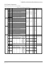
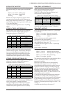
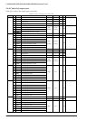
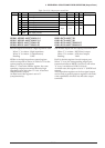
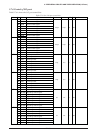
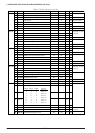
Table 5.6.4.1(b) Output port control bits
SR R/WAddress Bit Name Function Comment10
00FF76 D7
D6
D5
D4
D3
D2
D1
D0
–
–
–
–
R33D
R32D
R31D
R30D
R/W register
R/W register
R/W register
R/W register
R33 output port data
R32 output port data
R31 output port data
R30 output port data
Reserved register0
0
0
0
1
R/W
R/W
R/W
R/W
R/W
1
1
1
1
High
0
0
0
0
Low
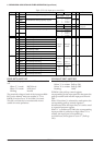
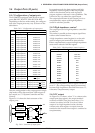
HZR0L, HZR0H: 00FF70H•D0, D1
HZR1L, HZR1H: 00FF70H•D2, D3
HZR20–HZR25: 00FF71H•D0–D5
HZR30–HZR33: 00FF72H•D0–D3
Sets the output terminals to a high impedance state.
When "1" is written: High impedance
When "0" is written: Complementary
Reading: Valid
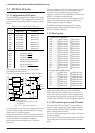
HZRxx is the high impedance control register
which correspond as shown in Table 5.6.2.1 to the
various output port terminals.
When "1" is set to the HZRxx register, the corre-
sponding output port terminal becomes high
impedance state and when "0" is set, it becomes
complementary output.
At initial reset, this register is set to "0"
(complementary).
R00D–R07D: 00FF73H
R10D–R17D: 00FF74H
R20D–R25D: 00FF75H•D0–D5
R30D–R33D: 00FF76H•D0–D3
Sets the data output from the output port terminal Rxx.
When "1" is written: HIGH level output
When "0" is written: LOW level output
Reading: Valid
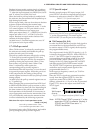
RxxD is the data register for each output port.
When "1" is set, the corresponding output port
terminal switches to HIGH (V
DD) level, and when
"0" is set, it switches to LOW (VSS) level.
At initial reset, this register is set to "1" (HIGH level
output).
The output data registers set for bus signal output
can be used as general purpose registers with read/
write capabilities which do not affect the output
terminals.