


76 EPSON S1C88650 TECHNICAL MANUAL
5 PERIPHERAL CIRCUITS AND THEIR OPERATION (Serial Interface)
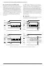
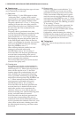
SMD0, SMD1: 00FF48H•D1, D2
Set the transfer modes according to Table 5.8.9.2.
Table 5.8.9.2 Transfer mode settings
SMD1 SMD0 Mode
1
1
0
0
1
0
1
0
Asynchronous 8-bit
Asynchronous 7-bit
Clock synchronous slave
Clock synchronous master
SMD0 and SMD1 can also read out.
At initial reset, this register is set to "0" (clock
synchronous master mode).
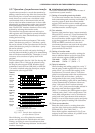
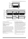
ESIF: 00FF48H•D0
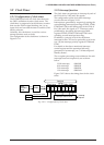
Sets the serial interface terminals (P10–P13).
When "1" is written:
Serial input/output terminal
When "0" is written: I/O port terminal
Reading: Valid
The ESIF is the serial interface enable register and
P10–P13 terminals become serial input/output
_________ _________
terminals (SIN, SOUT, SCLK, SRDY) when "1" is
written, and they become I/O port terminals when
"0" is written.
Also, see Table 5.8.3.2 for the terminal settings
according to the transfer modes.
At initial reset, ESIF is set to "0" (I/O port).
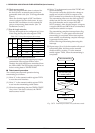
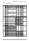
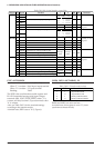
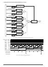
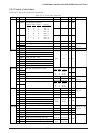
Table 5.8.9.1(b) Serial interface control bits
Address Bit Name SR R/WFunction Comment10
00FF20 D7
D6
D5
D4
D3
D2
D1
D0
PK01
PK00
PSIF1
PSIF0
–
–
PTM1
PTM0
Constantly "0" when
being read
0
0
–
–
0
R/W
R/W
R/W
–
–
–
–
K00–K07 interrupt priority register
Serial interface interrupt priority register
–
–
Clock timer interrupt priority register
PK01
PSIF1
1
1
0
0
Priority
level
PK00
PSIF0
1
0
1
0
Level 3
Level 2
Level 1
Level 0
PTM1
1
1
0
0
Priority level
PTM0
1
0
1
0
Level 3
Level 2
Level 1
Level 0
D7
D6
D5
D4
D3
D2
D1
D0
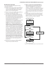
00FF23 –
–
–
–
–
ESERR
ESREC
ESTRA
–
–
–
–
–
Serial I/F (error) interrupt enable register
Serial I/F (receiving) interrupt enable register
Serial I/F (transmitting) interrupt enable register
–
–
–
–
–
0
–
–
–
–
–
Interrupt
enable
–
–
–
–
–
Interrupt
disable
Constantly "0" when
being read
R/W
00FF27 D7
D6
D5
D4
D3
D2
D1
D0
–
–
–
–
–
FSERR
FSREC
FSTRA
–
–
–
–
–
Serial I/F (error) interrupt factor flag
Serial I/F (receiving) interrupt factor flag
Serial I/F (transmitting) interrupt factor flag
–
–
–
–
–
0 R/W
–
–
–
–
–
(R)
Generated
(W)
Reset
–
–
–
–
–
(R)
No generated
(W)
No operation
Constantly "0" when
being read