


62 EPSON S1C88650 TECHNICAL MANUAL
5 PERIPHERAL CIRCUITS AND THEIR OPERATION (Serial Interface)
The serial interface terminals are configured
according to the transfer mode set using the
registers SMD0 and SMD1. SIN and SOUT are
serial data input and output terminals which
function identically in clock synchronous system
_________
and asynchronous system. SCLK is exclusively for
use with clock synchronous system and functions
as a synchronous clock input/output terminal.
_________
SRDY is exclusively for use in clock synchronous
slave mode and functions as a send-receive ready
signal output terminal.
_________
When asynchronous system is selected, since SCLK
_________
and SRDY are superfluous, the I/O port terminals
P12 and P13 can be used as I/O ports.
In the same way, when clock synchronous master
_________
mode is selected, since SRDY is superfluous, the
I/O port terminal P13 can be used as I/O port.
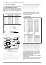
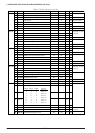
5.8.3 Transfer modes
There are four transfer modes for the serial inter-
face and mode selection is made by setting the two
bits of the mode selection registers SMD0 and
SMD1 as shown in the table below.
Table 5.8.3.1 Transfer modes
At initial reset, transfer mode is set to clock syn-
chronous master mode.
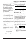
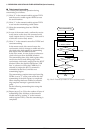
■ Clock synchronous master mode
In this mode, the internal clock is utilized as a
synchronous clock for the built-in shift registers,
and clock synchronous 8-bit serial transfers can be
performed with this serial interface as the master.
The synchronous clock is also output from the
_________
SCLK terminal which enables control of the
external (slave side) serial I/O device. Since the
_________
SRDY terminal is not utilized in this mode, it can be
used as an I/O port.
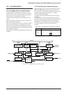
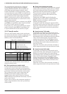
Figure 5.8.3.1(a) shows the connection example of
input/output terminals in the clock synchronous
master mode.
Table 5.8.3.2 Terminal settings corresponding
to each transfer mode
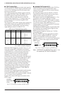
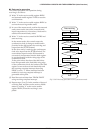
■ Clock synchronous slave mode
In this mode, a synchronous clock from the external
(master side) serial input/output device is utilized
and clock synchronous 8-bit serial transfers can be
performed with this serial interface as the slave.
_________
The synchronous clock is input to the SCLK
terminal and is utilized by this interface as the
synchronous clock.
_________
Furthermore, the SRDY signal indicating the
transmit-receive ready status is output from the
_________
SRDY terminal in accordance with the serial
interface operating status.
In the slave mode, the settings for registers SCS0
and SCS1 used to select the clock source are invalid.
Figure 5.8.3.1(b) shows the connection example of
input/output terminals in the clock synchronous
slave mode.
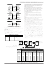
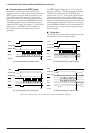
■ Asynchronous 7-bit mode
In this mode, asynchronous 7-bit transfer can be
performed. Parity check during data reception and
addition of parity bit (odd/even/none) during
transmitting can be specified and data processed in
7 bits with or without parity. Since this mode
_________
employs the internal clock, the SCLK terminal is
_________
not used. Furthermore, since the SRDY terminal is
not utilized either, both of these terminals can be
used as I/O ports.
Figure 5.8.3.1(c) shows the connection example of
input/output terminals in the asynchronous mode.
■ Asynchronous 8-bit mode
In this mode, asynchronous 8-bit transfer can be
performed. Parity check during data reception and
addition of parity bit (odd/even/none) during
transmitting can be specified and data processed in
8 bits with or without parity. Since this mode
_________
employs the internal clock, the SCLK terminal is
_________
not used. Furthermore, since the SRDY terminal is
not utilized either, both of these terminals can be
used as I/O ports.
Figure 5.8.3.1(c) shows the connection example of
input/output terminals in the asynchronous mode.
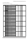
SMD1 SMD0 Mode
1
1
0
0
1
0
1
0
Asynchronous 8-bit
Asynchronous 7-bit
Clock synchronous slave
Clock synchronous master
Mode SIN
Asynchronous 8-bit
Asynchronous 7-bit
Clock synchronous slave
Clock synchronous master
P13
P13
Output
P13
SOUT SCLK SRDY
P12
P12
Input
Output
Output
Output
Output
Output
Input
Input
Input
Input