


74 EPSON S1C88650 TECHNICAL MANUAL
5 PERIPHERAL CIRCUITS AND THEIR OPERATION (Serial Interface)
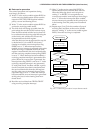
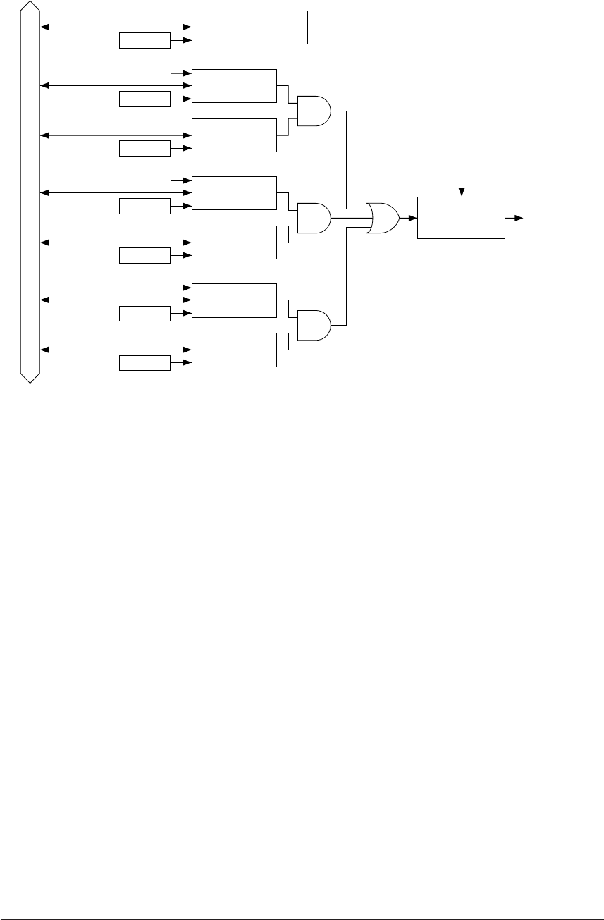
Data bus
Interrupt
request
Address
Error generation
Interrupt factor
flag FSERR
Address
Interrupt enable
register ESERR
Address
Receive completion
Interrupt factor
flag FSREC
Address
Interrupt enable
register ESREC
Address
Transmit completion
Interrupt factor
flag FSTRA
Address
Interrupt enable
register ESTRA
Interrupt priority
level judgement
circuit
Address
Interrupt priority
register PSIF0, PSIF1
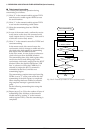
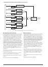
■ Receiving complete interrupt
This interrupt factor is generated at the point where
receiving has been completed and the receive data
incorporated into the shift register has been trans-
ferred into the received data buffer and it sets the
interrupt factor flag FSREC to "1". When set in this
manner, if the corresponding interrupt enable
register ESREC is set to "1" and the corresponding
interrupt priority registers PSIF0 and PSIF1 are set to
a higher level than the setting of interrupt flags (I0
and I1), an interrupt will be generated to the CPU.
When "0" has been written into the interrupt enable
register ESREC and interrupt has been disabled, an
interrupt is not generated to the CPU. Even in this
case, the interrupt factor flag FSREC is set to "1".
The interrupt factor flag FSREC is reset to "0" by
writing "1".
The generation of this interrupt factor permits the
received data to be read.
Also, the interrupt factor flag is set to "1" when a
parity error or framing error is generated.
The exception processing vector address is set as
follows:
Receiving complete interrupt: 00002AH.
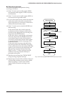
■ Error interrupt
This interrupt factor is generated at the point where
a parity error, framing error or overrun error is
detected during receiving and it sets the interrupt
factor flag FSERR to "1". When set in this manner, if
the corresponding interrupt enable register ESERR
is set to "1" and the corresponding interrupt priority
registers PSIF0 and PSIF1 are set to a higher level
than the setting of interrupt flags (I0 and I1), an
interrupt will be generated to the CPU.
When "0" has been written in the interrupt enable
register ESERR and interrupt has been disabled, an
interrupt is not generated to the CPU. Even in this
case, the interrupt factor flag FSERR is set to "1".
The interrupt factor flag FSERR is reset to "0" by
writing "1".
Since all three types of errors result in the same
interrupt factor, you should identify the error that
has been generated by the error flags PER (parity
error), OER (overrun error) and FER (framing
error).
The exception processing vector address is set as
follows:
Receive error interrupt: 000028H.
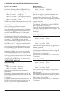
Fig. 5.8.8.1 Configuration of serial interface interrupt circuit