


90 EPSON S1C88650 TECHNICAL MANUAL
5 PERIPHERAL CIRCUITS AND THEIR OPERATION (Programmable Timer)
Compare data register
The programmable timer has a built-in data
comparator so that count data can be compared
with an optional value. The compare data register
(CDRx) is used to set the value to be compared.
In the 8-bit mode, CDRx is used as an 8-bit register
separated for each timer.
In the 16-bit mode, the CDR(L) register is handled
as low-order 8 bits of compare data, and the
CDR(H) register is as high-order 8 bits.
The compare data register can be read and written,
and all the registers are set to 00H at initial reset.
The programmable timer compares count data
with the compare data register (CDRx), and
generates a compare match signal when they
become the same value. This compare match signal
generates an interrupt, and controls the clock
(TOUTx signal) output.
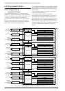
Timer operation
Timer is equipped with PTRUNx register which
controls the RUN/STOP of the timer. Timer x
starts down counting by writing "1" to the
PTRUNx register. However, it is necessary to
control the input clock and to preset the reload
data before starting a count.
When "0" is written to PTRUNx register, clock
input is prohibited, and the count stops.
This RUN/STOP control does not affect data in the
counter. The data in the counter is maintained
during count deactivation, so it is possible to
resume counting from the data.
In the 8-bit mode, the timers can be controlled
individually by the PTRUNx register.
In the 16-bit mode, the PTRUN(L) register controls
a pair of timers as a 16-bit timer. In this case,
control of the PTRUN(H) register is invalid.
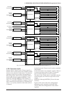
The buffers PTMx is attached to the counter, and
reading is possible in optional timing.
When the counter agrees with the data set in the
compare data register during down counting, the
timer generates a compare match interrupt.
And, when the counter underflows, an underflow
interrupt is generated, and the initial value set in
the reload data register is loaded to the counter.
The interrupt generated does not stop the down
counting.
After an underflow interrupt is generated, the
counter continues counting from the initial value
reloaded.
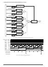
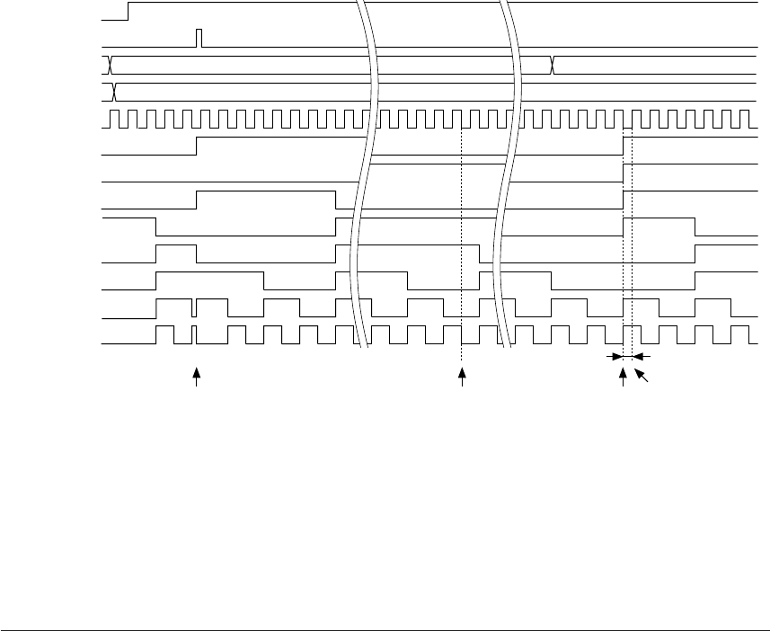
PTRUNx
PSETx
RDRx
CDRx
Input clock
PTMx7
PTMx6
PTMx5
PTMx4
PTMx3
PTMx2
PTMx1
PTMx0
A6H
58H
A6H
58H 58H
F3H
Preset Underflow interrupt
generation
Reload
∗1
Compare match
interrupt generation
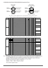
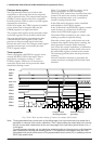
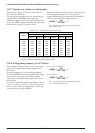
Fig. 5.10.4.1 Basic operation timing of counter (an example of 8-bit mode)
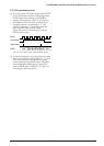
Note: The programmable timer counts down at the falling edge of the input clock and at the same time it
generates an interrupt if the counter underflows. Then it starts loading the reload data to the counter
and the counter data is determined at the next rising edge of the input clock (period shown in as
∗
1
in the figure).
To avoid improper reloading, do not rewrite the reload data after an interrupt occurs until the counter
data is determined including the reloading period
∗
1. Be especially careful when using the OSC1
(low-speed clock) as the clock source of the programmable timer and the CPU is operating with the
OSC3 (high-speed clock).