


S1C88650 TECHNICAL MANUAL EPSON 125
5 PERIPHERAL CIRCUITS AND THEIR OPERATION (SVD Circuit)
5.12.3 Control of SVD circuit
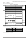
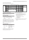
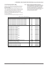
Table 5.12.3.1 shows the SVD circuit control bits.
Table 5.12.3.1 SVD circuit control bits
Address Bit Name SR R/WFunction Comment10
00FF12 D7
D6
D5
D4
D3
D2
D1
D0
–
–
SVDDT
SVDON
SVDS3
SVDS2
SVDS1
SVDS0
–
–
SVD detection data
SVD circuit On/Off
SVD criteria voltage setting
Constantly "0" when
being read
–
–
0
0
0
0
0
0
R
R/W
R/W
R/W
R/W
R/W
–
–
Low
On
–
–
Normal
Off
SVDS3
1
1
1
:
0
SVDS2
1
1
1
:
0
SVDS1
1
1
0
:
1
SVDS0
1
0
1
:
1
Voltage (V)
2.7
2.6
2.5
:
1.8
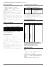
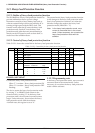
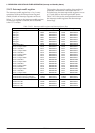
SVDS3–SVDS0: 00FF12H•D3–D0
Criteria voltage for SVD is set as shown in Table
5.12.2.1.
At initial reset, this register is set to "0".
SVDON: 00FF12H•D4
Controls the SVD circuit ON and OFF.
When "1" is written: SVD circuit ON
When "0" is written: SVD circuit OFF
Reading: Valid
When the SVDON register is set to "1", a supply
voltage detection is executed by the SVD circuit. As
soon as SVDON is reset to "0", the result is loaded
to the SVDDT latch. To obtain a stable detection
result, the SVD circuit must be ON for at least 500
µsec.
At initial reset, this register is set to "0".
SVDDT: 00FF12H•D5
This is the result of supply voltage detection.
When "0" is read: Supply voltage (V
DD–VSS)
≥ Criteria voltage
When "1" is read: Supply voltage (VDD–VSS)
< Criteria voltage
Writing: Invalid
The result of supply voltage detection at time of
SVDON is set to "0" can be read from this latch.
At initial reset, SVDDT is set to "0".
5.12.4 Programming notes
(1) To obtain a stable detection result, the SVD
circuit must be ON for at least 500 µsec. So, to
obtain the SVD detection result, follow the
programming sequence below.
1. Set SVDON to "1"
2. Maintain for 500 µsec minimum
3. Set SVDON to "0"
4. Read SVDDT
(2) The SVD circuit should normally be turned OFF
because SVD operation increase current con-
sumption.