


S1C88650 TECHNICAL MANUAL EPSON 81
5 PERIPHERAL CIRCUITS AND THEIR OPERATION (Clock Timer)
5.9 Clock Timer
5.9.1 Configuration of clock timer
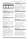
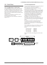
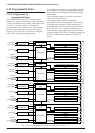
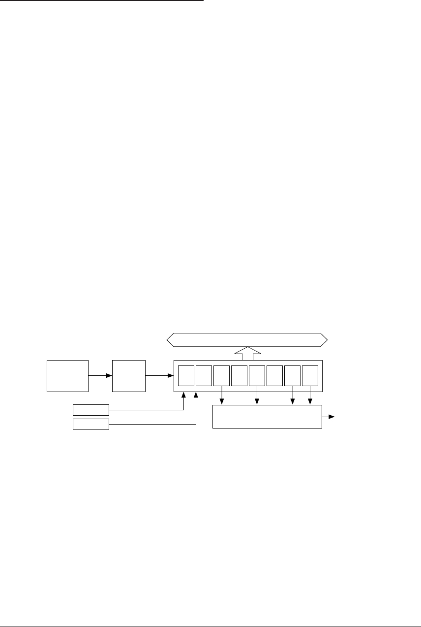
The S1C88650 has built in a clock timer that uses
the OSC1 oscillation circuit as clock source. The
clock timer is composed of an 8-bit binary counter
that uses the 256 Hz signal dividing fOSC1 as its
input clock and can read the data of each bit (128–1
Hz) by software.
Normally, this clock timer is used for various
timing functions such as clocks.
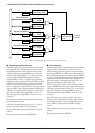
The configuration of the clock timer is shown in
Figure 5.9.1.1.
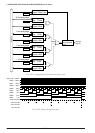
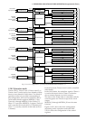
5.9.2 Interrupt function
The clock timer can generate an interrupt by each of
the 32 Hz, 8 Hz, 2 Hz and 1 Hz signals.
The configuration of the clock timer interrupt
circuit is shown in Figure 5.9.2.1.
Interrupts are generated by respectively setting the
corresponding interrupt factor flags FTM32, FTM8,
FTM2 and FTM1 at the falling edge of the 32 Hz, 8
Hz, 2 Hz and 1 Hz signals to "1". Interrupt can be
prohibited by the setting the interrupt enable
registers ETM32, ETM8, ETM2 and ETM1 corre-
sponding to each interrupt factor flag.
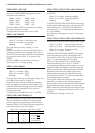
In addition, a priority level of the clock timer
interrupt for the CPU can be optionally set at levels
0 to 3 by the interrupt priority registers PTM0 and
PTM1.
For details on the above mentioned interrupt
control register and the operation following
generation of an interrupt, see "5.14 Interrupt and
Standby Status".
The exception processing vector addresses for each
interrupt factor are respectively set as shown
below.
32 Hz interrupt: 000034H
8 Hz interrupt: 000036H
2 Hz interrupt: 000038H
1 Hz interrupt: 00003AH
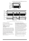
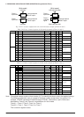
Figure 5.9.2.2 shows the timing chart for the clock
timer.
Data bus
Interrupt
request
Interrupt control circuit
OSC1
oscillation
circuit
64
Hz
32
Hz
16
Hz
8
Hz
4
Hz
2
Hz
1
Hz
128
Hz
Clock timer reset
TMRST
Clock timer
TMD0–TMD7
TMRUN
Clock timer Run/Stop
Divider
fOSC1 256 Hz
Fig. 5.9.1.1 Configuration of clock timer