


168 EPSON S1C88650 TECHNICAL MANUAL
APPENDIX A S5U1C88000P1&S5U1C88649P2 MANUAL (Peripheral Circuit Board for S1C88650)
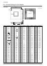
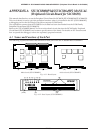
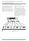
A.3 Connecting to the Target System
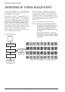
This section explains how to connect the S5U1C88000P1&S5U1C88649P2 to the target system.
Note: Turn the power of all equipment off before connecting or disconnecting cables.
Use the I/O cables (80-pin/40-pin × 2 flat type,
100-pin/50-pin × 2 flat type, 40-pin/20-pin × 2 flat
type) to connect between the I/O #1 to I/O #4
connectors of the front panel and the target
system.
Connect the 80-pin, 100-pin and 40-pin cable
connectors to the I/O #1 to I/O #4 connectors, and
the 40-pin × 2, 50-pin × 2 and 20-pin × 2 connectors
to the target system. Be careful as power (VDD) is
supplied to I/O #1, I/O #2 and I/O #3 connectors.
The following shows the clock frequencies
generated from the on-board crystal oscillation
circuits:
OSC1 crystal oscillation circuit: 32.768 kHz
OSC3 crystal oscillation circuit: 4.9152 MHz
When CR oscillation is selected, the oscillation
frequency can be adjusted using the controls on
the front panel (OSC1H and OSC1L for adjusting
OSC1, OSC3H and OSC3L for adjusting OSC3).
Use a frequency counter or other equipment to be
connected to the OSC1 CR oscillation frequency
monitor pin (pin 18) on the monitor connector or
OSC3 CR oscillation frequency monitor pin (pin
19) for monitoring the frequency during adjust-
ment. Be sure of the frequency when using this
monitor pin because the CR oscillation frequency
is initially undefined.
POWER
EMU
SLP/HALT
RESET
TRGOUT
STOPOUT
TRCIN
BRKIN
GND
ICE88UR
E0C88 Family In-Circuit Emulator
ON/OFF
DIAG
RESET
MONITOR
L
S5U1C88000P1
S1C88 Family Peripheral circuit board
EPSON
I/O #2I/O #1
H
OSC3
LH
OSC1
VSVDVLCD
LCD 8
7654321
161514131211109
CN1-1
(40-pin)
Target board
I/O #1
(80-pin)
CN2-1
(40-pin)
I/O #2
(80-pin)
CN2-2
(40-pin)
CN1-2
(40-pin)
CN3-1
(20-pin)
CN3-2
(20-pin)
CN4-1
(50-pin)
CN4-2
(50-pin)
CN1-1 CN2-1 CN2-2CN1-2CN3-1CN3-2 CN4-1 CN4-2
I/O #4
(100-pin)
I/O #3
(40-pin)
Fig. A.3.1 Connecting to the target system