


S1C88650 TECHNICAL MANUAL EPSON 79
5 PERIPHERAL CIRCUITS AND THEIR OPERATION (Serial Interface)
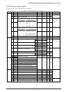
FER: 00FF49H•D6
Indicates the generation of a framing error.
When "1" is read: Error
When "0" is read: No error
When "1" is written: Reset to "0"
When "0" is written: Invalid
FER is an error flag that indicates the generation of
a framing error and becomes "1" when an error has
been generated.
When the stop bit for the receiving of the asynchro-
nous mode has become "0", a framing error is
generated.
FER is reset to "0" by writing "1".
At initial reset and when RXEN is "0", FER is set to
"0" (no error).
PSIF0, PSIF1: 00FF20H•D4, D5
Sets the priority level of the serial interface interrupt.
The two bits PSIF0 and PSIF1 are the interrupt
priority register corresponding to the serial inter-
face interrupt. Table 5.8.9.4 shows the interrupt
priority level which can be set by this register.
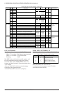
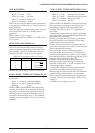
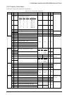
Table 5.8.9.4 Interrupt priority level settings
PSIF1 PSIF0 Interrupt priority level
1
1
0
0
1
0
1
0
Level 3 (IRQ3)
Level 2 (IRQ2)
Level 1 (IRQ1)
Level 0 (None)
At initial reset, this register is set to "0" (level 0).
ESTRA, ESREC, ESERR: 00FF23H•D0, D1, D2
Enables or disables the generation of an interrupt
for the CPU.
When "1" is written: Interrupt enabled
When "0" is written: Interrupt disabled
Reading: Valid
ESTRA, ESREC and ESERR are interrupt enable
registers that respectively correspond to the inter-
rupt factors for transmitting complete, receiving
complete and receiving error. Interrupts set to "1"
are enabled and interrupts set to "0" are disabled.
At initial reset, this register is set to "0" (interrupt
disabled).
FSTRA, FSREC, FSERR: 00FF27H•D0, D1, D2
Indicates the serial interface interrupt generation status.
When "1" is read: Interrupt factor present
When "0" is read:
Interrupt factor not present
When "1" is written: Resets factor flag
When "0" is written: Invalid
FSTRA, FSREC and FSERR are interrupt factor flags
that respectively correspond to the interrupts for
transmitting complete, receiving complete and
receiving error and are set to "1" by generation of
each factor.
Transmitting complete interrupt factor is generated
at the point where the data transmitting of the shift
register has been completed.
Receiving complete interrupt factor is generated at
the point where the received data has been trans-
ferred into the received data buffer.
Receive error interrupt factor is generated when a
parity error, framing error or overrun error has been
detected during data receiving.
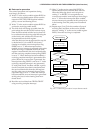
When set in this manner, if the corresponding
interrupt enable register is set to "1" and the corre-
sponding interrupt priority register is set to a higher
level than the setting of interrupt flags (I0 and I1), an
interrupt will be generated to the CPU.
Regardless of the interrupt enable register and
interrupt priority register settings, the interrupt
factor flag will be set to "1" by the occurrence of an
interrupt generation condition.
To accept the subsequent interrupt after interrupt
generation, re-setting of the interrupt flags (set
interrupt flag to lower level than the level indicated
by the interrupt priority registers, or execute the
RETE instruction) and interrupt factor flag reset are
necessary. The interrupt factor flag is reset to "0" by
writing "1".
At initial reset, this flag is reset to "0".