


S1C88650 TECHNICAL MANUAL EPSON 131
5 PERIPHERAL CIRCUITS AND THEIR OPERATION (Interrupt and Standby Status)
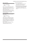
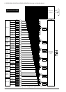
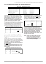
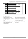
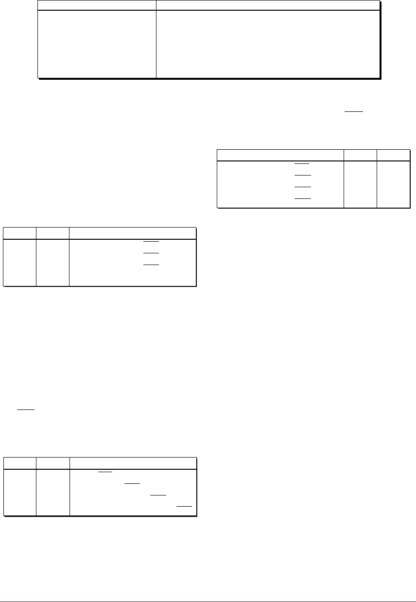
5.14.4 Interrupt priority register and interrupt priority level
Table 5.14.4.1 Interrupt priority register
Interrupt
K00–K07 input interrupt
Programmable timer interrupt 1–0
Programmable timer interrupt 3–2
Programmable timer interrupt 5–4
Programmable timer interrupt 7–6
Serial interface interrupt
Clock timer interrupt
PK00, PK01
PPT0, PPT1
PPT2, PPT3
PPT4, PPT5
PPT6, PPT7
PSIF0, PSIF1
PTM0, PTM1
00FF20·D6, D7
00FF21·D2, D3
00FF21·D4, D5
00FF2A·D0, D1
00FF2A·D2, D3
00FF20·D4, D5
00FF20·D0, D1
Interrupt priority register
The interrupt priority registers shown in Table
5.14.4.1 are set to each system of interrupts and the
interrupt priority levels for the CPU can be set to
the optional priority level (0–3). As a result, it is
possible to have multiple interrupts that match the
system's interrupt processing priority levels.
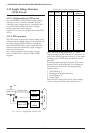
The interrupt priority level between each system
can optionally be set to three levels by the interrupt
priority register. However, when more than one
system is set to the same priority level, they are
processed according to the default priority level.
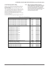
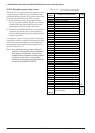
Table 5.14.4.2 Setting of interrupt priority level
P*1P*0
Interrupt priority level
1
1
0
0
1
0
1
0
Level 3 (IRQ3)
Level 2 (IRQ2)
Level 1 (IRQ1)
Level 0 (None)
At initial reset, the interrupt priority registers are
all set to "0" and each interrupt is set to level 0.
Furthermore, the priority levels in each system
have been previously decided and they cannot be
changed.
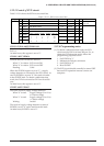
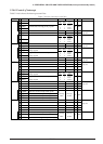
The CPU can mask each interrupt by setting the
interrupt flags (I0 and I1). The relation between the
interrupt priority level of each system and interrupt
flags is shown in Table 5.14.4.3, and the CPU
accepts only interrupts above the level indicated by
the interrupt flags.
The NMI (watchdog timer) that has level 4 priority,
is always accepted regardless of the setting of the
interrupt flags.
Table 5.14.4.3 Interrupt mask setting of CPU
I1 I0
Acceptable interrupt
1
1
0
0
1
0
1
0
Level 4 (NMI)
Level 4, Level 3 (IRQ3)
Level 4, Level 3, Level 2 (IRQ2)
Level 4, Level 3, Level 2, Level 1 (IRQ1)
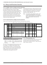
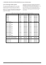
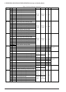
After an interrupt has been accepted, the interrupt
flags are written to the level of that interrupt.
However, interrupt flags after an NMI has been
accepted are written to level 3 (I0 = I1 = "1").
Table 5.14.4.4 Interrupt flags after acceptance of interrupt
I1 I0
Accepted interrupt priority level
1
1
1
0
1
1
0
1
Level 4 (NMI)
Level 3 (IRQ3)
Level 2 (IRQ2)
Level 1 (IRQ1)
The set interrupt flags are reset to their original
value on return from the interrupt processing
routine. Consequently, multiple interrupts up to 3
levels can be controlled by the initial settings of the
interrupt priority registers alone. Additional
multiplexing can be realized by rewriting the
interrupt flags and interrupt enable register in the
interrupt processing routine.
Note: Beware. If the interrupt flags have been
rewritten (set to lower priority) prior to
resetting an interrupt factor flag after an
interrupt has been generated, the same
interrupt will be generated again.