


Switcher Software, cont’d
MPX Plus 866 A Media Presentation Matrix Switcher • Switcher Software
5-8
PRELIMINARY
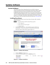
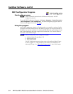
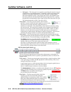
Program audio input signal controls (
a
)
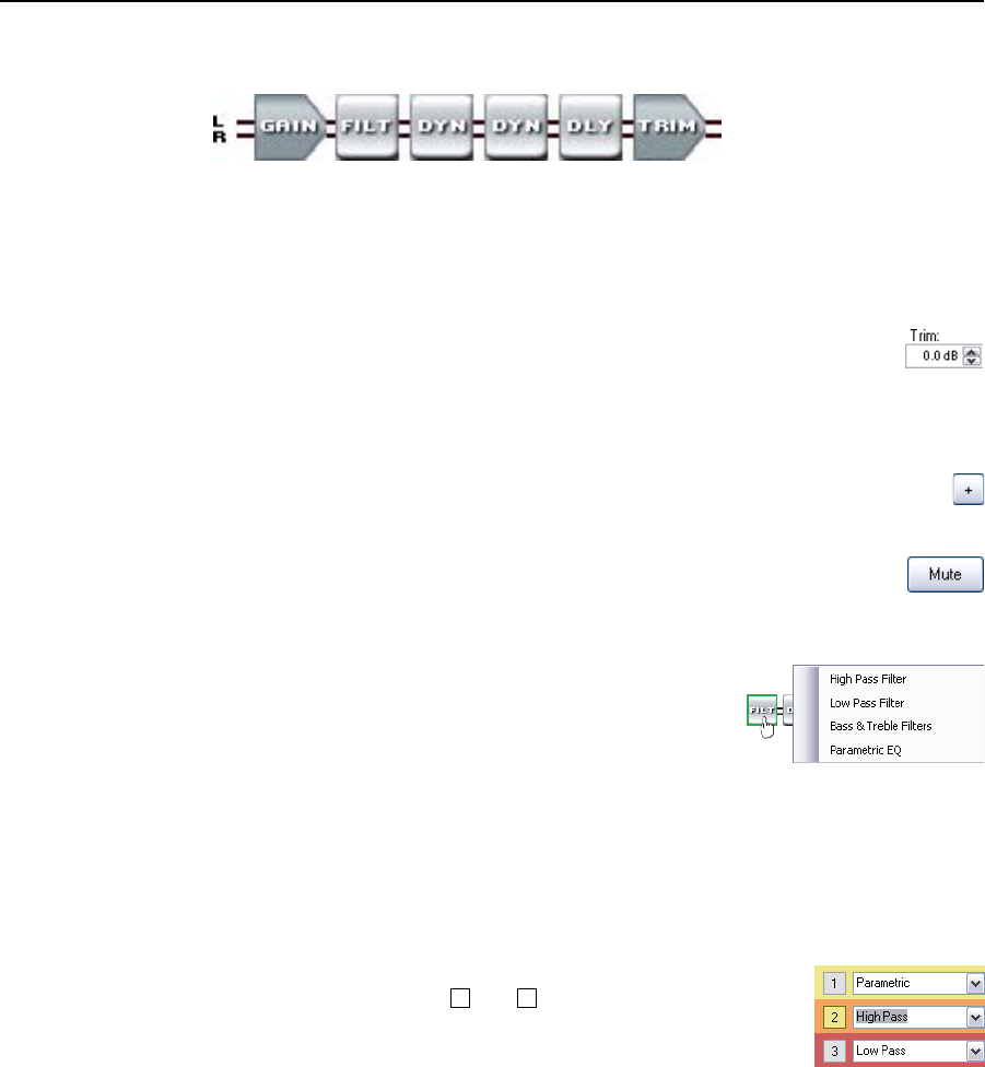
The program audio input signal processor chain makes adjustments to program
audio material before it is tied to specific outputs.
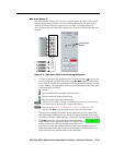
Gain control — The always-present gain control provides the same basic audio
input level adjustments that are available from the front panel (see “Viewing and
adjusting the input audio level“, in chapter 3, “Operation”).
Additionally, the left and right input channels each have trim controls,
accessible in the dialog box, for separate fine adjustment with a gain
range of -6 dB to +6 dB in 0.1 dB increments. The default setting is
unity gain (0.0 dB).
N
The trim settings are not indicated in the front panel display.
The Polarity buttons, accessible in the dialog box, let you flip the polarity of
the wires connected to the audio connectors (+/tip and -/ring) to easily
correct for miswired connectors.
The Mute buttons, accessible in the dialog box, let you separately
silence the left and right audio channels. If you mute both channels,
audio is completely silent on that input. When one or both channels are
muted, one or two red indicator(s) in the block turn on.
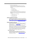
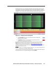
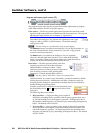
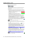
Filter block —
The filter processor block, when first
inserted, provides one of four filter selections;
additional filters can then be added. A filter
attenuates (removes) or boosts a range of frequencies
from an audio waveform, while passing other
frequencies. Click the desired filter to select it.
N
Selecting “Bass & Treble Filter” inserts two separate filters.
Additional filters, for a total of up to three filters, can then be added by double-
clicking the processor block. Additionally, each filter’s frequency range can
be changed in the dialog box, customized to the filter, that can be accessed by
double-clicking the processor block.
To add a second and/or third filter to the filter block, select
the desired filter in the
2
and
3
drop-down boxes in the
dialog box.
The following filters are available:
• High pass filter — A high pass filter passes a band of
frequencies extending from a specified cutoff frequency (greater than zero)
up toward the high-end of the frequency spectrum. All frequencies above
the specified cutoff frequency are allowed to pass, attenuating all frequencies
below. The default cutoff is 100 Hz.
• Low pass filter — A low pass filter passes a band of frequencies extending
from a specified cutoff frequency (less than infinite) down toward the low
end of the frequency spectrum. All frequencies below the specified cutoff
frequency are allowed to pass, attenuating all frequencies above. The default
cutoff is 10 kHz