


Switcher Software, cont’d
MPX Plus 866 A Media Presentation Matrix Switcher • Switcher Software
5-10
PRELIMINARY
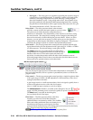
• Noisegate— The noise gate is an expander, expanding the dynamic range of
a signal below a specified threshold. To simplify, it makes soft signals softer,
effectively removing background noise while allowing a stronger signal,
above the threshold, to pass. Using a high ratio of 20:1, the expander closes
the audio path below the threshold, eliminating background noise, opening
the path above the threshold to allow signal to pass; hence the term noise gate.
The default threshold is -65 dB. The ratio is 20.0:1.
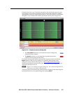
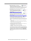
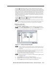
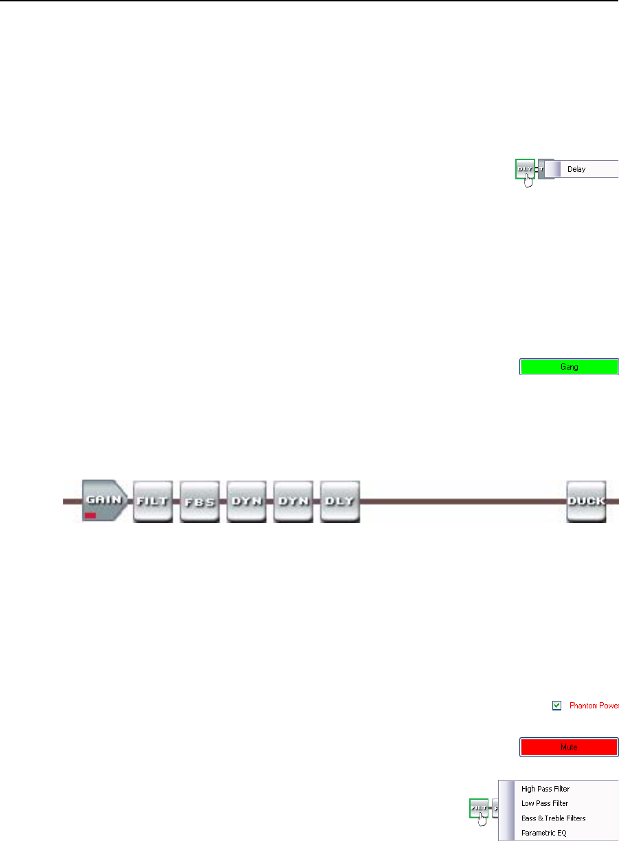
Delay block — The delay processor block, when inserted,
provides a means to delay the audio signal to sync it to video.
The processor can delay the audio using either time or
distance as a determiner. The default delay, when inserted, is at 100 ms, using
the time function. The delay block’s settings can be changed in the dialog box
that can be accessed by double-clicking the processor block. When you select
distance, you can select feet or meters; at which point you can also specify a
temperature, in either degrees Fahrenheit or degrees Centigrade. The processor
calculates the change in speed of sound for the specified temperature.
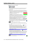
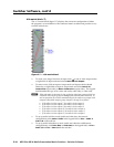
Trim control — The always-present trim control provides separate left and right
input channel faders for fine adjustment with a gain range of -12 dB to +12 dB in
0.1 dB increments. The default setting is unity gain (0.0 dB).
The Gang button lets you couple the left and right faders.
Gangedfadersmovetogetheratrelativelevelstothetopor
bottom of their travel. If one fader reaches the limit of its
travel first, it retains that position while the other fader continues to travel.
When the ganged faders travel in the reverse direction, the fader that was at its
limit reverts to its position relative to the other fader.
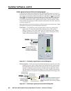
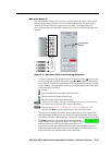
Mic/line input signal controls (
b
)
The mic/line input signal processor chain makes adjustments to microphone or
line level audio material, such as a speaker’s presentation, before it is mixed with
program audio.
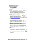
Gain control — The always-present gain control provides a single long-throw fader
with a gain range of 0 dB to +80 dB, adjustable in 1 dB increments, with a level
setting readout below the fader.
A gain range from 0 to +10 dB accommodates a line level signal, typically from a
wireless microphone receiver with a line level output.
Above +10 dB, the input switches to a mic level input.
The Phantom Power checkbox, accessible in the dialog box, lets you
toggle +48 VDC phantom power on and off, typically to power a condenser mic.
The Mute button, accessible in the dialog box,
let you silence the mic/line input.
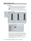
Filter block —
The filter processor block, when first
inserted, provides one of four filter selections;
additional filters can be then be added. The available
filters and adding additional filters are identical to as
described on the program audio input in the filter
processor block (except that up to five filters total can be selected for this block).
See “Program audio input signal controls (
a
)“.
N
Selecting “Bass & Treble Filter” inserts two separate filters.