


4-15
MPX Plus 866 A Media Presentation Matrix Switcher • SIS Programming and Control
PRELIMINARY
Command ASCII command
(host to switcher)
Response
(switcher to host)
Additional
description
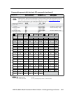
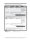
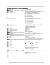
View ties, gain, volume, mutes, presets, file status, DSVP, and input status (continued)
View video preset
configuration
EX1)
*1*1VC
} X!
1
•
X!
2
•
X!
3
•...•
X!
16
•Vid
]
Show preset
X1)
’s video
configuration. Show the video
input tied to 12 sequential
outputs, starting from output
1. (Video outputs 13 through
16 are not present on this
switcher model.)
Command description:
Response description:
Preset# * starting output# (StO# [“1” for this switcher]) * 1(=video) VC
Input#(I#)tiedtooutput#(O#)1•I#tiedtoO#2•I#tiedtoO#3•...•I#tiedtoO#16•Vid
]
Example:
E
4*1*1VC
}
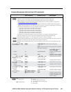
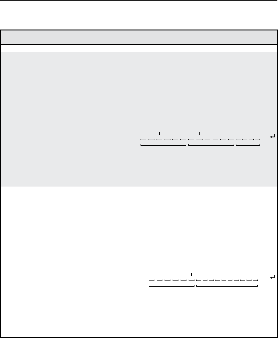
01Output:
Response = tied input:
Input 4 tied to output 3
02 03 04 05 06 07
08•08•04•08•08•00•09•00•10•10•10•10•--•--•--•--•Vid
13
No tied input
Computer/Audio Group Video Group
Outputs not present
14 15 1608 09 10 11 12
Each position shown in the response is an output: left = starting, right = output 12 (outputs 13 through 16 are not
present on this switcher model). The number in each position is the input tied to that output.
Video — Input 8 is tied to outputs 1, 2, 4, and 5; input 4 to output 3; input 9 to output 7; and input 10 to outputs 10
through 12. No input is tied to outputs 6 and 8.
N
If you enter
EX1)
*1*1VC
}
where
X1)
= 0, the switcher returns its current video configuration.
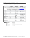
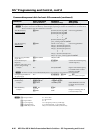
View audio preset
configuration
EX1)
*1*2VC
} X!
1
•
X!
2
•
X!
3
•...•
X!
16
•Aud
]
Show preset
X1)
’s audio
configuration. Show
the audio input tied to 6
sequential outputs, starting
from output 1. (Audio
outputs 7 through 16 are
not present on this switcher
model.)
Command description:
Response description:
Preset# * starting output# (StO# [“1” for this switcher]) * 2(=audio) VC
I#tiedtoO#1•I#tiedtoO#2•I#tiedtoO#3•I#tiedtoO#4...•I#tiedtoO#16•Aud
]
Example:
E
4*1*2VC
}
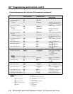
01Output:
Response = tied input:
Input 6 tied to output 3
02 03 04 05 06
02•04•06•08•10•12•--•--•--•--•--•--•--•--•--•--•Aud
13
Input 12 tied to output 6
Computer/Audio
Group
Outputs not
present
14 15 16
07 08 09 10 11 12
Each position shown in the response is an output: left = starting, right = output 6 (outputs 7 through 16 are not
present on this switcher model). The number in each position is the input tied to that output.
Audio — Input 2 is tied to output 1, input 4 is tied to output 2, input 6 is tied to output 3, input 8 is tied to output 4,
input 10 is tied to output 5, and input 12 is tied to output 6.
N
If you enter
EX1)
*1*2VC
}
where
X1)
= 0, the switcher returns its current audio configuration.
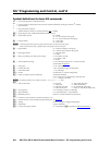
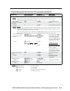
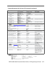
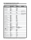
Command/response table for basic SIS commands (continued)
N
X!
= Input number 00 or 01 – 14
X1)
= Preset # 32 maximum (0 = current configuration)