


Switcher Software, cont’d
MPX Plus 866 A Media Presentation Matrix Switcher • Switcher Software
5-30
PRELIMINARY
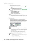
DSP capacity and design rule verification
DSP capacity
Each processor, when inserted, uses a portion of the DSP’s total processing power.
• Theamountofprocessingpowerfortheblockisconstant,unchangedby
parameter settings or whether it is bypassed or not.
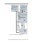
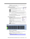
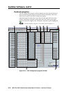
• Processorsintheprogram audio input (computer/audio group and video/
audio group) processor chains (
a
, on figure 5-3) are active (using processor
power) only when tied to an output.
• Processorsintheprogramaudioinput(
a
) and line output (
d
and
f
) are
stereo processors, each using two of that processor type.
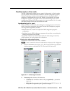
The DSP Configurator program calculates the processor usage of all active
processors in the line output (
d
and
f
) and mic input (
e
) processor chains and
the six most processor-intensive input processors (
a
), depending on the
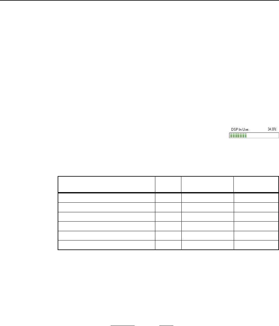
configuration. The program displays a DSP usage meter that
shows the results of this usage calculation.
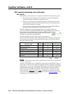
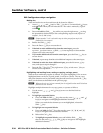
The following table shows the DSP usage for each processor
type, the maximum number of processors that can be active within a configuration
or current state/emulation, and the potential DSP usage if all of those processors
are active at the same time.
P
rocessor type
D
SP
usage
M
aximum # of
active processors
P
otential total
DSP usage
D
ynamic processors
0
.4%
4
4
17.2%
D
ucking blocks
1
.6%
4
6.3%
D
elays
1
.9%
2
8
54.3%
F
BS blocks (dynamic filters only)
1
0.6%
4
42.4%
A
ll filters (including fixed FBS filters)
0
.1%
2
08
22.9%
L
oudness
0
.3%
1
2
3.1%
T
otal:
146.2%
N
DSP usage percentages do not exactly add up to the totals due to rounding to the
nearest 0.1%.
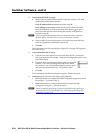
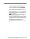
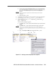
The DSP can overload when a combination of processors is enabled that totals over
100% usage. In this case, the switcher can lock up and fail to operate, necessitating
cycling power. As part of its monitoring of DSP usage, when the DSP Configurator
program detects that usage is nearing the 100% threshold, it makes uninserted
processor blocks unavailable for insertion. This prevents an overload caused by
normal operation. However, you can recall a combination of partial presets that
causes an overload. The design rule verification function (see the next page), when
used properly, can avoid an overload.