


5-15
MPX Plus 866 A Media Presentation Matrix Switcher • Switcher Software
PRELIMINARY
Mic mixer block (
e
)
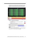
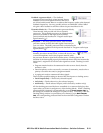
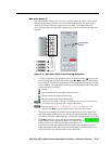
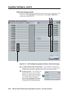
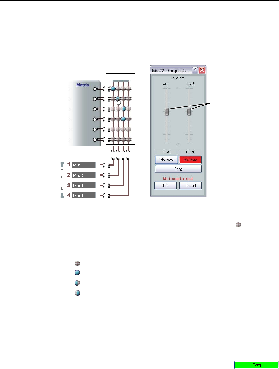
The mic mixer block (figure 5-8), an array of points where mic audio can be mixed
into the output audio, provides a way to unmute and mute the normally muted
inputs from the mic/line input signal processor chain. Unmuting effectively
mixes the mic inputs into the audio outputs at the level set in the left and right mix
controls.
Mic Mixer
Level Control
Faders
Figure 5-8 — Mic mixer block and mic mixing dialog box
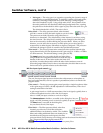
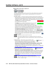
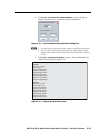
• Tomuteorunmuteamic,double-clickoneofthemix-points( ) to open a mic
mixing dialog box. Click the left and/or right Mic Mute buttons in the dialog
box to unmute or mute the applicable mic/line input into the left and/or right
output channel. The appearance of the mix-point indicates the mic/line input
connection status as follows:
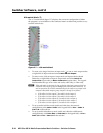
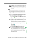
Muted
Mixed into both (left and right) output channels
Mixed into the left output channel only
Mixed into the right output channel only
N
Unlike from line inputs 1 through 14 (typically program audio), more than one
mic audio input can be mixed into a single audio output.
N
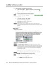
Note the message “Mic is muted at input!” in figure 5-8. This
indicates that Mute is selected in the mic/line input gain control block.
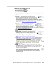
• Themicmixingdialogboxincludeslevelcontrolsthatprovideseparateleft
and right output channel faders for mix (level) adjustment with a gain range
of -35 dB to +25 dB in 1 dB increments. The default setting is unity gain (0 dB).
• TheGang button lets you couple the left and right faders.
Gangedfadersmovetogetheratrelativelevelstothetopor
bottom of their travel. If one fader reaches the limit of its
travel first, it retains that position while the other fader continues to travel.
When the ganged faders travel in the reverse direction, the fader that was at
its limit reverts to its position relative to the other fader.