


Installation, cont’d
MPX Plus 866 A Media Presentation Matrix Switcher • Installation
2-10
PRELIMINARY
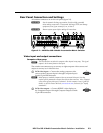
Front Panel Configuration Port
AUDIO
VIDEO
I/O
CONTROL
ENTER PRESET
VIEW
ESC
PRESENTATION MATRIX SWITCHER
MPX PLUS 866 A
CONFIG
1
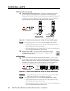
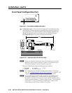
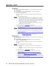
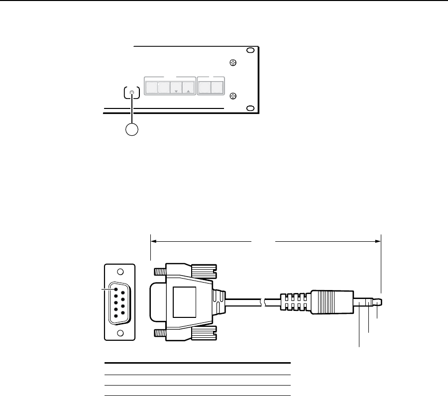
Figure 2-9 — Front panel configuration port
a
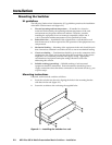
Configuration port — This 2.5 mm mini stereo jack serves the same serial
communications function as the rear panel Remote port, but it is easier to
access than the rear port after the matrix switcher has been installed and
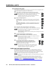
cabled. The optional 9-pin D to 2.5 mm stereo mini TRS RS-232 cable,
part #70-335-01 (figure 2-10) can be used for this connection.
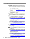
6 feet
(1.8 m)
Part #70-335-01
5
1
9
6
Sleeve (Gnd)
Ring
Tip
9-pin D Connection TRS Plug
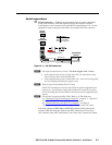
Pin 2 Computer's RX line Tip
Pin 3 Computer's TX line Ring
Pin 5 Computer's signal ground Sleeve
Figure 2-10 — Optional 9-pin TRS RS-232 cable
N
This port is completely separate from the rear panel Remote port and is not
affected by changes to the rear panel port’s protocol. This front panel port’s
protocol can be changed, under SIS command control only.
This port is RS-232 only, with its default protocols as follows:
• 9600baud • noparity • 8-bit
• 1stopbit • noowcontrol
N
The Configuration port can operate at 9600, 19200, 38400, or 115200 baud
rates. See “Command/Response table for IP SIS commands”, in chapter 4, “SIS
Programming and Control”, to configure all ports under SIS control.
N
The maximum distances from the matrix switcher to the controlling device
can vary up to 200 feet (61 m). Factors such as cable gauge, baud rates,
environment, and output levels (from the switcher and the controlling device)
all affect transmission distance. Distances of about 50 feet (15 m) are typically
not a problem. In some cases the matrix switcher may be capable of serial
communications via RS-232 up to 250 feet (76 m) away.