


SIS
™
Programming and Control, cont’d
MPX Plus 866 A Media Presentation Matrix Switcher • SIS Programming and Control
4-8
PRELIMINARY
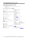
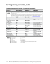
Symbol definitions for basic SIS commands
]
= CR/LF (carriage return/line feed) (hex 0D 0A)
}
= Carriage return (no line feed, hex 0D) (for URL-encoded commands, use the pipe character,
|
, instead)
• = Space character
|
= Pipe (vertical bar) character
* = Asterisk character (which is a command character, not a variable)
E
= Escape key (hex 1B) (use W instead of Esc for Web browsers)
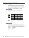
X!
= Input number (for tie) 00 = untied
01 – 08 = the computer video group
09 – 14 = the low resolution video group
X@
= Output number 01 – 12 for video
01 – 06 for audio
N
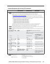
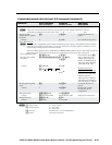
A video input from either of the two groups cannot be tied to an output in the other group.
Audio can be tied to any output, regardless of the video group to which it was input.
X#
= Input number 01 – 08 for the computer video group
09 – 14 for the low resolution video group
X$
= Input signal format 1 = composite video
2 = S-video
X%
= Mute, pre-peaking, Lock mode, power supply 0 = off/mode 0/not OK
1 = on/mode 1/OK
2 = mode 2
X^
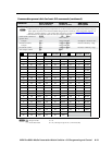
= Volume adjustment range 0 – 64 (1 dB/step except for 0-to-1, which is 34.5 dB)
(see the table on page 4-11)
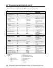
X&
= Audio gain 0 – 24 (1 dB/step)
X*
= Numeric dB value -18 to +24 (45 steps of gain or attenuation)
X(
= Audio attenuation 1 – 18 (1 dB/step)
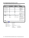
X1)
= Preset # 32 maximum (0 = current configuration)
X1!
= Name (for presets, inputs, and outputs) 12 characters maximum
Upper- and lower-case alphanumeric characters and
_ : = / and space are valid.
N
The following characters are invalid in the name: ~ , @ ‘ [ ] { } < > ’ “ ; | \ and ?.
X1@
= Video/audio mute: 0 = no mutes 4 = audio right (AR) mute
1 = video mute 5 = video and AR mute
2 = audio left (AL) mute 6 = AL and AR (all audio) mute
3 = video and AL mute 7 = video, AL, and AR (all audio) mute
X1#
= Sync frequency xxx.xx (frequency in Hz (V) or kHz (H))
X1$
= Signal detection 0 = no input detected, 1 = input detected
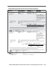
X1%
= RGBdelayinterval Delayin½secondincrements(10maximum)
X1^
= Firmware version number to second decimal place (x.xx)
X1&
= Verbose firmware version-description-upload date/time. See page 4-18.
X1*
= Voltage Positive or negative voltage and magnitude
X1(
= Temperature Degrees Fahrenheit
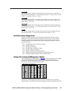
X2)
= Groupmastergroupnumber 01-32(repeatedas
X6$
in appendix B,”DSP SIS Commands”)