


2-5
MPX Plus 866 A Media Presentation Matrix Switcher • Installation
PRELIMINARY
Audio inputs (both input groups)
h
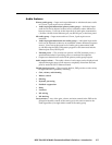
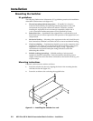
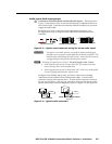
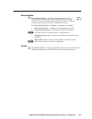
Connections for balanced and unbalanced audio inputs — Each input has a
5-pole, 3.5 mm captive screw connector for balanced or unbalanced stereo or
mono audio input. Connectors are included with the switcher, but you must
supply the audio cable.
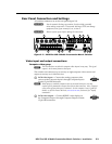
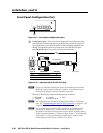
See figure 2-3 to wire a connector for the appropriate input type. Use
the supplied tie-wrap to strap the audio cable to the extended tail of the
connector.
L R
L R
Unbalanced Stereo Input
Balanced Stereo Input
Do not tin the wires!
Ring
Sleeve (s)
Tip
Sleeve
Tip
Sleeve
Tip
Tip
Ring
Figure 2-3 — Captive screw connector wiring for stereo audio inputs
C
The captive screw audio connector can easily be inadvertently plugged
partially into one receptacle and partially into an adjacent receptacle. This
misconnection could damage the audio circuits. Ensure that the connector
is plugged fully and only into the desired input or output.
N
The length of exposed wires is critical. The ideal length is 3/16" (5 mm).
• Ifthestrippedsectionofwireislongerthan3/16", the exposed wires may
touch, causing a short circuit between them.
• Ifthestrippedsectionofwireisshorterthan3/16", wires can be easily pulled
out even if tightly fastened by the captive screws.
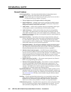
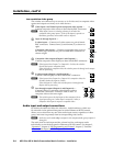
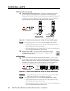
See figure 2-4 to identify the tip, ring, and sleeve when you are making
connections for the switcher from existing audio cables. A mono audio
connector consists of the tip and sleeve. A stereo audio connector consists of
the tip, ring and sleeve. The ring, tip, and sleeve wires are also shown on the
captive screw audio connector diagrams, figure 2-3, figure 2-5, and figure 2-6.
Tip (+)
Sleeve ( )
Sleeve ( )
Ring (
-
)
Tip (+)
RCA Connector
3.5 mm Stereo Plug Connector
(balanced)
Figure 2-4 — Typical audio connectors